
Connecting a low-voltage microcontroller circuit directly to a high-voltage or electrically noisy system, such as mains power or an industrial motor, is a fast way to damage sensitive components or even put a person at risk.
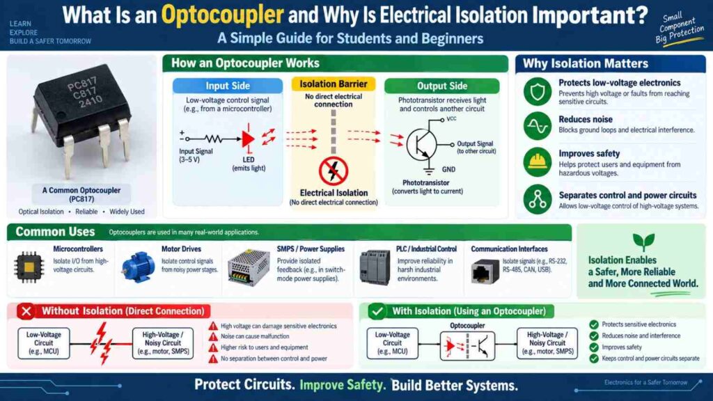
The optocoupler exists precisely to prevent that, allowing two circuits to communicate without any direct electrical connection between them.
This article explains what an optocoupler is, how it achieves electrical isolation using light, and why that isolation matters so much in real electronic and industrial designs.
What an Optocoupler Is
An optocoupler, sometimes called an opto-isolator, is a component that transfers an electrical signal from one circuit to another using light rather than a direct electrical connection.
Inside a typical optocoupler package are two main parts: a light-emitting diode, or LED, on the input side, and a light-sensitive receiver, commonly a phototransistor, on the output side.
When an electrical signal drives the LED, it emits light proportional to that signal, and the phototransistor on the other side detects this light and reproduces a corresponding electrical signal in the second circuit, all without the two circuits ever sharing a direct electrical path.
How Signal Transfer Happens Without an Electrical Connection
The key to understanding an optocoupler is recognizing that light, unlike electrical current, can cross a physical gap without requiring conductive material. Inside the optocoupler’s sealed package, a transparent or translucent gap separates the LED from the phototransistor.
Current flowing through the LED on the input side causes it to emit light across this gap, and the phototransistor on the output side responds to that light by conducting current in its own separate circuit.
This means the input and output sides of the optocoupler can operate at completely different voltage levels, and even different ground references, while still passing a signal between them reliably.
Why Electrical Isolation Matters
Electrical isolation protects circuits and people from several real dangers. Without isolation, a fault or voltage surge in a high-voltage section of a circuit could travel directly into a low-voltage microcontroller section, destroying sensitive components instantly.
Isolation also prevents ground loops, which occur when two circuits with slightly different ground reference points are connected directly, causing unwanted current flow and noisy or inaccurate signals.
In systems involving mains voltage, generators, or industrial motor drives, isolation is often not just good practice but a safety requirement, protecting both equipment and the people operating it.
Common Optocoupler Applications
| Application | What Is Isolated | Why It Matters |
|---|---|---|
| Microcontroller to relay driver | Low-voltage logic from switched load voltage | Protects the microcontroller from voltage spikes |
| Mains voltage sensing circuits | Mains AC from low-voltage control circuit | Prevents dangerous voltage reaching the control side |
| PLC digital input modules | Field wiring from internal PLC logic | Protects industrial controllers from field faults |
| Motor drive control signals | Control electronics from motor power stage | Reduces electrical noise interference |
| Solar charge controller feedback | Battery-side voltage from control logic | Prevents ground loop issues between sections |
Optocouplers in Nigerian Power and Industrial Systems
Given the prevalence of generators, inverters, and solar installations across Nigeria, optocouplers play a quiet but important role in many systems students will encounter. Generator automatic voltage regulators often use optocouplers to isolate sensing circuits from the higher power sections they monitor.
Inverter systems commonly use them to isolate control logic from the switching power stage. In industrial settings, PLC input and output modules, discussed in our PLC programming article, rely heavily on optocoupler-based isolation to protect the controller from noisy or faulty field wiring on a factory floor, which is a major reason PLCs are so robust in harsh environments.
Interfacing an Optocoupler in a Basic Circuit
Wiring an optocoupler correctly involves treating the input and output sides as genuinely separate circuits, since that separation is the entire point of using the component.
- Connect the LED side of the optocoupler to your control circuit, typically through a current-limiting resistor, exactly as you would wire any standard LED.
- Connect the phototransistor side to the separate circuit being controlled, such as a relay driver or a sensing circuit on the higher-voltage side.
- Keep the ground references of the two sides separate; connecting them together defeats the purpose of using an optocoupler.
- Check the optocoupler’s datasheet for its current transfer ratio, which describes how much output current you can expect for a given input current, since this affects circuit design.
- Test the isolated output independently to confirm it responds correctly to the input signal before integrating it into a larger project.
Choosing the Right Optocoupler for a Project
Not all optocouplers are identical, and selecting the right one depends on the switching speed needed, the isolation voltage rating required, and whether the output side needs to switch significant current directly or simply provide a logic-level signal.
For general-purpose student projects involving relay driving or simple isolated sensing, basic phototransistor-output optocouplers are usually sufficient and are widely available and inexpensive from local electronics component dealers.
Common Misconceptions
- “An optocoupler is the same as a simple transistor switch.” A transistor switch still shares a common electrical connection between control and load circuits, while an optocoupler provides genuine electrical isolation with no direct electrical path at all.
- “Isolation is only necessary for very high voltage circuits.” Even circuits operating at moderate voltages benefit from isolation to prevent ground loops, reduce noise, and protect sensitive components from unexpected faults.
- “Optocouplers slow down every circuit they’re used in.” While there is some inherent switching delay, many optocouplers are fast enough for typical control and communication applications and are specifically rated for higher-speed use when needed.
Frequently Asked Questions
Can an optocoupler transmit an analog signal, or only digital on/off signals?
Optocouplers are most commonly used for digital on/off signaling, but linear optocouplers do exist that can transmit analog signals with reasonable accuracy for specific applications.
What happens if the two sides of an optocoupler share a common ground by mistake?
Connecting the grounds together removes the electrical isolation the optocoupler is meant to provide, potentially exposing the low-voltage side to fault currents or noise from the other circuit.
Are optocouplers only used with mains-level voltages?
No, optocouplers are also widely used between low-voltage circuits, such as isolating a microcontroller’s logic section from a motor driver’s power section, purely to prevent electrical noise and ground loop issues.
Final Thoughts
Optocouplers solve a problem that becomes unavoidable as soon as a project mixes sensitive low-voltage electronics with higher-voltage or electrically noisy power stages: how to pass a signal between the two without exposing one side to the risks of the other.
By transmitting signals as light across a physical gap rather than through a direct wire connection, optocouplers deliver genuine electrical isolation that protects both equipment and people.
From generator voltage regulators to PLC input modules to simple relay driver circuits in student projects, this small component quietly makes countless Nigerian electrical and industrial systems safer and more reliable.