
The diode is often the very first semiconductor component a student encounters in an electronics course, and for good reason: it introduces the fundamental idea that makes almost all modern electronics possible, controlling the direction current is allowed to flow.
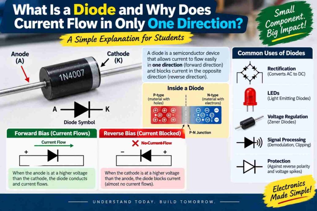
From protecting circuits against reversed battery connections to forming the backbone of rectifiers, diodes are everywhere. This article explains what a diode is, how it works at a basic level, and why current only flows through it in one direction.
What a Diode Is
A diode is a two-terminal semiconductor device that allows electric current to flow easily in one direction while blocking it almost entirely in the opposite direction. The two terminals are called the anode and the cathode, and current flows from anode to cathode when the diode is forward biased, meaning voltage is applied in the direction that encourages conduction.
When the voltage is applied in the opposite direction, called reverse bias, the diode blocks nearly all current flow, behaving almost like an open switch. This simple one-way behavior is what makes diodes so useful across countless circuit designs.
How a Diode Works Internally
A standard diode is made by joining two types of semiconductor material, commonly silicon, that have been treated, or doped, to have different electrical properties.
One side, called P-type material, has an abundance of positive charge carriers called holes. The other side, called N-type material, has an abundance of negative charge carriers, or electrons. Where these two materials meet forms what is called a P-N junction.
When forward biased, the applied voltage pushes electrons and holes toward the junction, where they combine and allow current to flow continuously across it. When reverse biased, the applied voltage pulls electrons and holes away from the junction, widening a region depleted of charge carriers and effectively blocking current flow.
Why Current Flows in Only One Direction
The one-directional behavior comes directly from this P-N junction structure. Forward bias narrows the depletion region at the junction and allows charge carriers to cross freely once the applied voltage exceeds a certain threshold, typically around 0.7 volts for common silicon diodes.
Reverse bias widens the depletion region and creates an effective barrier that charge carriers cannot easily cross, so for all practical purposes, no significant current flows. This is a physical property of the semiconductor junction itself, not something achieved through switches or moving parts, which is part of why diodes are so reliable and long-lasting components.
Types of Diodes and Their Uses
While the basic silicon diode is the most common type, several specialized diode variants exist, each optimized for a particular application.
| Diode Type | Key Property | Common Use |
|---|---|---|
| Standard rectifier diode | Blocks reverse current reliably | AC to DC conversion, discussed in our rectifier article |
| Light-emitting diode (LED) | Emits light when forward biased | Indicator lights, displays, lighting |
| Zener diode | Conducts in reverse above a set voltage | Voltage regulation and reference circuits |
| Schottky diode | Lower forward voltage drop, fast switching | High-efficiency power circuits |
| Photodiode | Generates current when exposed to light | Light sensing applications |
Common Diode Applications in Practical Circuits
Diodes solve several distinct problems across circuit design, and recognizing these use cases helps make sense of why a diode appears in a particular schematic.
- Rectification, converting AC to DC in power supplies, as explained fully in our rectifier and half-wave versus full-wave rectifier articles.
- Reverse polarity protection, preventing damage if a battery or power supply is connected backward, a common safeguard in Nigerian solar and inverter setups.
- Voltage regulation, using Zener diodes to hold a steady reference voltage in a circuit.
- Signal demodulation, extracting information from a modulated radio frequency signal.
- Free-wheeling or flyback protection, absorbing voltage spikes generated when current through an inductive load like a motor or relay coil is suddenly interrupted.
Testing a Diode with a Multimeter
Verifying whether a diode is working correctly is a common troubleshooting task in labs and field repairs. Most digital multimeters include a dedicated diode test mode, indicated by a diode symbol on the dial.
Connecting the meter’s probes across the diode in the forward direction should show a voltage drop reading, typically around 0.6 to 0.7 volts for silicon diodes, indicating the diode conducts properly.
Reversing the probes should show an open circuit reading, usually displayed as “OL” or a similar overload indicator, confirming the diode blocks current in that direction. A diode that conducts in both directions, or in neither direction, is faulty and should be replaced.
Diodes in Nigerian Student Projects
Diodes are inexpensive, widely available from local electronics dealers, and appear in nearly every practical project a Nigerian electrical or electronics student builds, from a simple LED circuit on a breadboard to protection circuitry in a SIWES industrial training build or a solar charge controller final year project.
Understanding diode behavior well is also a prerequisite for understanding transistors, discussed in our dedicated transistor article, since transistors are built from similar semiconductor junction principles extended into a three-terminal device.
Common Misconceptions
- “A diode completely blocks all current in the reverse direction.” A diode blocks nearly all current in reverse bias under normal conditions, but a very small leakage current still flows, and exceeding the diode’s reverse breakdown voltage can cause it to conduct heavily and potentially fail.
- “All diodes behave identically.” Different diode types, such as Zener, Schottky, and standard rectifier diodes, are engineered with different properties for very different applications.
- “A diode has no voltage drop when conducting.” A forward-biased diode always has a small but real voltage drop across it, typically around 0.7 volts for silicon diodes, which must be accounted for in circuit design.
Frequently Asked Questions
What happens if a diode is connected backward in a circuit?
In reverse bias, the diode blocks current flow almost entirely, so the circuit typically will not function as intended, though this behavior is deliberately used in reverse polarity protection circuits.
What is the difference between a diode and an LED?
An LED is a specific type of diode that emits visible light when forward biased, while the term diode more broadly covers any device with this one-directional current behavior, including types that do not emit light.
Why do diodes have a forward voltage drop?
The forward voltage drop reflects the energy needed to push charge carriers across the P-N junction’s depletion region, and this value depends on the semiconductor material used, typically around 0.7 volts for silicon and about 0.3 volts for germanium.
Final Thoughts
The diode’s simple but powerful one-way behavior, rooted in the physics of the P-N junction, underlies an enormous range of electronic functions, from rectifying AC power to protecting circuits and regulating voltage.
Understanding forward and reverse bias, recognizing the different diode types, and knowing how to test one with a multimeter equips you to both design and troubleshoot real circuits confidently.
As a foundational semiconductor component, the diode also sets the stage for understanding more complex devices like transistors, making it well worth mastering thoroughly early in your electronics studies.