
Most people picture a transformer as a large device that changes voltage on the power grid, but a huge number of transformers in any electrical system exist purely to measure current safely, not to supply power to a load. These are current transformers, small but essential devices found in nearly every metering panel, protection relay, and switchgear cubicle.
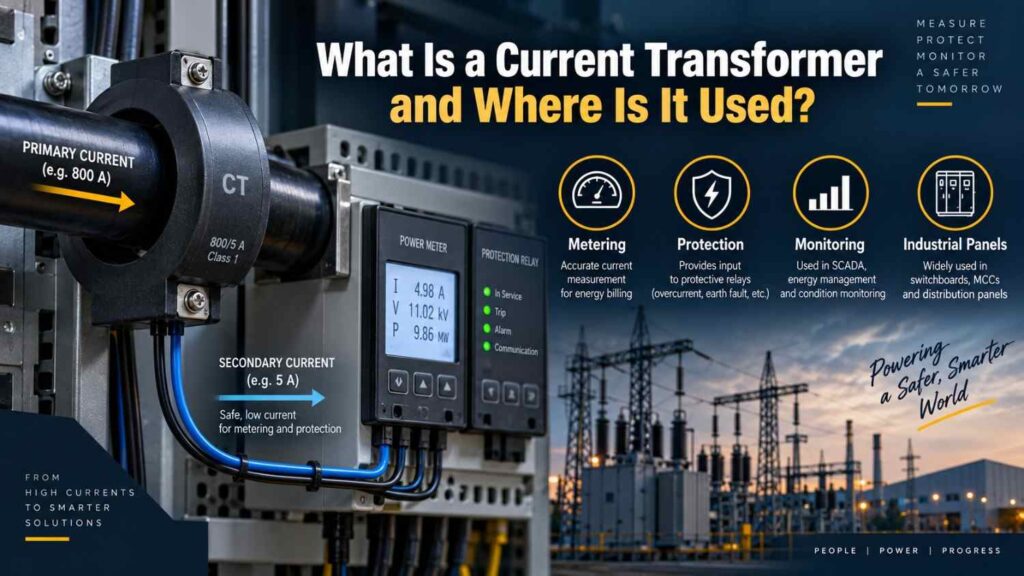
This article explains what a current transformer is, how it differs in purpose from a power transformer, and where it shows up in real installations.
What a Current Transformer Does
A current transformer, commonly abbreviated CT, takes a large current flowing through a primary conductor and produces a proportionally scaled-down current on its secondary winding, small enough to be safely measured or fed into protection relays. A typical distribution CT might have a ratio of 200:5, meaning 200 amps flowing in the primary produces 5 amps on the secondary.
This scaled-down signal drives ammeters, energy meters, and protection relays without those devices ever having to handle the full primary current directly, which would otherwise require dangerously heavy, expensive instrumentation.
How a Current Transformer Is Built and Works
Unlike a power transformer, which is built for efficient energy transfer, a current transformer is built purely for accurate current ratio and phase relationship. The primary “winding” is often just the busbar or cable passing once through the CT’s core, sometimes called a bar-type or window-type CT, while the secondary winding is wound with many turns around a laminated core.
The turns ratio between primary and secondary determines the current transformation ratio, following the same basic transformation principle covered in our dedicated article on what a transformer is, just applied to current measurement rather than power delivery.
Where Current Transformers Are Used
CTs appear anywhere current needs to be measured or monitored without directly connecting sensitive equipment to high current circuits. Common applications include:
- Energy metering at DisCo customer connections and utility revenue meters
- Protection relays that trip circuit breakers during overcurrent or fault conditions
- Ammeters on switchgear panels showing real-time load current
- Motor protection systems monitoring current for overload and phase imbalance
- Power quality and harmonic analysers that need a safe, scaled current signal
- Differential protection schemes on transformers and feeders comparing current at two points
Types of Current Transformers
Current transformers are generally grouped by construction and by accuracy purpose. Bar-type CTs have a fixed primary conductor built through the core, typically used for high current applications. Window-type or ring-type CTs have an opening through which an existing cable or busbar is passed, making them easy to retrofit onto existing installations.
Wound-type CTs have a distinct primary winding with more than one turn, used for lower current ratings where a single-pass primary would not produce enough magnetising effect. Separately, CTs are also classified by purpose: metering-class CTs are optimised for accuracy at normal load, while protection-class CTs are designed to remain accurate even during large fault currents, when metering-class CTs would saturate and lose accuracy.
Current Transformer Accuracy Classes
Accuracy matters differently depending on whether the CT is used for billing or protection, and standards reflect that distinction.
| CT Purpose | Typical Accuracy Class | Key Requirement |
|---|---|---|
| Revenue metering | 0.2 to 0.5 | High accuracy at normal load for fair billing |
| Indicating instruments | 1.0 to 3.0 | Reasonable accuracy for panel display |
| Protection relays | 5P or 10P class | Accurate performance during high fault current |
Why Current Transformers Matter for Grid Reliability
Protection relays only act as fast and as correctly as the current signal feeding them, so a CT with the wrong ratio, saturated core, or degraded insulation can cause a protection relay to under-react to a real fault or over-react to normal load changes.
On the Nigerian grid, where TCN transmission infrastructure and DisCo distribution networks depend heavily on protection coordination to isolate faults quickly and limit outage scope, correctly specified and well-maintained CTs are a quiet but critical part of keeping the wider network stable.
Revenue metering CTs also directly affect billing accuracy, which matters for utilities working to reduce commercial losses from inaccurate metering.
Common Problems With Current Transformers in the Field
A handful of practical issues account for most CT-related problems technicians encounter. Incorrect ratio selection for the actual load current leads to poor accuracy at both ends of the measurement range. Saturation during high fault current can distort the secondary signal exactly when protection relays need it most, which is why protection-class CTs are specifically designed to resist this.
Wiring errors, particularly reversed polarity, cause incorrect readings or relay maloperation. Perhaps the most dangerous field issue, though, is leaving a CT’s secondary circuit open while current still flows in the primary, a hazard serious enough to deserve its own dedicated article on current transformer secondary safety.
Common Misconceptions
- “A current transformer is just a small power transformer.” CTs are designed around accurate current ratio and low burden, not efficient power transfer, and they behave very differently under fault or open-circuit conditions.
- “Any CT can be used for both metering and protection.” Metering-class CTs are optimised for accuracy at normal load and saturate during faults, while protection-class CTs are built to stay accurate specifically during high fault current.
- “CT secondary current is dangerous because it’s electrically live like the primary.” The secondary current is scaled down and low in magnitude under normal closed-circuit operation; the real danger arises specifically when the secondary circuit is left open.
Frequently Asked Questions
What does a CT ratio like 100:5 actually mean?
It means that when 100 amps flows through the primary conductor, the CT produces 5 amps on its secondary winding, a ratio used to scale instrument and relay readings back up to the actual primary current.
Can a current transformer be used on both AC and DC circuits?
No, conventional current transformers rely on alternating magnetic flux to induce a secondary current, so they only work on AC circuits; DC current measurement requires different technology such as Hall-effect sensors.
How is a current transformer different from a voltage transformer?
They measure different quantities and are wired differently into the circuit, a distinction explained fully in our dedicated article comparing current transformers and voltage transformers.
Final Thoughts
Current transformers rarely get the attention that large power transformers do, yet they form the backbone of accurate metering and reliable protection throughout an electrical network.
Understanding how they work, where they are applied, and the accuracy classes that separate metering from protection use gives technicians and engineers a clearer picture of why a seemingly small component carries such outsized importance.
In a grid like Nigeria’s, where protection coordination and billing accuracy both depend on correctly functioning CTs, treating these devices with the same seriousness as the larger equipment they support pays off in fewer nuisance trips and more accurate revenue collection.