
Once you understand what a rectifier does, discussed in detail in our dedicated rectifier article, the next natural question is which type to use in a given circuit.
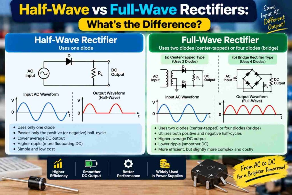
The two fundamental configurations you will meet in almost every electronics course are the half-wave rectifier and the full-wave rectifier. They both convert AC to DC, but they differ significantly in efficiency, component count, and output quality.
This article compares them directly so you can understand exactly when and why each one is used.
How a Half-Wave Rectifier Works
A half-wave rectifier is the simplest possible rectifier circuit, built using just a single diode. During the half of the AC cycle when the voltage pushes current in the diode’s forward direction, the diode conducts and current flows to the load.
During the other half of the cycle, when the voltage reverses, the diode blocks current entirely, so no current flows to the load during that portion. The result is an output that only uses half of the original AC waveform, with the other half simply discarded as if it never existed.
How a Full-Wave Rectifier Works
A full-wave rectifier makes use of both halves of the AC cycle instead of discarding one. There are two common ways to achieve this. A center-tapped full-wave rectifier uses two diodes along with a transformer that has a center-tapped secondary winding, so that one diode conducts during each half of the cycle.
A bridge rectifier achieves the same result using four diodes arranged in a specific configuration, without requiring a center-tapped transformer at all. In both cases, current is delivered to the load during both halves of the AC cycle, with the negative half effectively “flipped” to add to the output rather than being wasted.
Side-by-Side Comparison
| Characteristic | Half-Wave Rectifier | Full-Wave Rectifier |
|---|---|---|
| Diodes required | 1 | 2 (center-tapped) or 4 (bridge) |
| AC cycle utilized | Only one half | Both halves |
| Output ripple frequency | Same as input frequency | Twice the input frequency |
| Efficiency | Lower | Higher, roughly double |
| Output smoothness before filtering | More pulsating, larger gaps | Less pulsating, smaller gaps |
| Transformer requirement | Simple transformer | Center-tapped (or none for bridge) |
| Typical use | Low-power, simple applications | Most practical power supplies |
Why Full-Wave Rectifiers Are More Efficient
Because a half-wave rectifier only uses half of the incoming AC waveform, it wastes the other half entirely, resulting in a lower average output voltage and more pronounced gaps in the output where no current flows at all.
A full-wave rectifier captures energy from the entire AC cycle, resulting in a higher average output voltage for the same input, a smoother output waveform, and less demanding requirements on the filter capacitor needed to smooth the result.
This is why the vast majority of real power supplies, including phone chargers, laptop adapters, and inverter charging circuits common across Nigerian homes, use full-wave rectification, almost always in the bridge configuration.
Ripple and Why It Matters
Ripple refers to the small residual variation that remains in a DC output after rectification and filtering, since no rectifier and filter combination produces a perfectly flat voltage.
A half-wave rectifier produces ripple at the same frequency as the input AC, meaning the gaps between pulses are longer and require a larger filter capacitor to smooth adequately.
A full-wave rectifier produces ripple at twice the input frequency, since it delivers a pulse for both halves of the cycle, which means the gaps are shorter and a smaller capacitor can achieve similarly smooth output. This matters directly for component selection and cost in real designs.
Practical Circuit-Building Steps
Building and comparing both rectifier types on a breadboard is a valuable lab exercise for understanding the difference beyond the theory.
- Build a half-wave rectifier using a single diode connected to a step-down transformer and observe the output on an oscilloscope or by measuring average voltage with a multimeter.
- Build a bridge rectifier using four diodes, or a single bridge rectifier module, connected to the same transformer, and compare the output waveform.
- Add a filter capacitor to each circuit in turn and note how much smoother the full-wave output becomes with a smaller capacitor compared to the half-wave version.
- Measure the average DC output voltage of each configuration and note the noticeably higher value from the full-wave circuit.
- Record your observations carefully, since this comparison is a common practical assessment in first and second year electrical engineering courses.
Choosing Between Half-Wave and Full-Wave in a Design
In practice, half-wave rectifiers are rarely used in serious power supply designs today because of their poor efficiency and rougher output, though they still appear in simple, low-cost, low-power applications such as basic battery trickle chargers or signal detection circuits where efficiency is not a priority.
Full-wave bridge rectifiers, being compact, efficient, and available as a single low-cost integrated component, are the standard choice for nearly every practical AC to DC conversion task, including the power supplies inside inverters and the charging stages discussed in our solar charge controllers article.
Common Misconceptions
- “A half-wave rectifier is just a weaker version of a full-wave rectifier.” They are structurally different circuits; a half-wave rectifier discards half the AC cycle entirely, while a full-wave rectifier actively uses both halves to produce output.
- “A bridge rectifier needs a special transformer.” Unlike the center-tapped full-wave design, a bridge rectifier works with an ordinary transformer secondary winding, which is one reason it has become the more popular choice.
- “More diodes always mean a more complicated, less reliable circuit.” Bridge rectifier modules package four diodes into a single reliable component, making full-wave rectification just as simple to implement in practice as a half-wave design.
Frequently Asked Questions
Which rectifier type produces less ripple, half-wave or full-wave?
Full-wave rectifiers produce less ripple because they generate output pulses twice as often within the same time period, leaving smaller gaps for a filter capacitor to smooth over.
Is a bridge rectifier a type of full-wave rectifier?
Yes, a bridge rectifier is one of the two common ways to build a full-wave rectifier, and it is generally preferred because it does not require a center-tapped transformer.
Why would anyone still use a half-wave rectifier today?
Half-wave rectifiers are occasionally used in very simple, low-power, or low-cost applications where efficiency and smooth output are not critical priorities, though full-wave designs dominate most practical power supplies.
Final Thoughts
Half-wave and full-wave rectifiers both accomplish the same basic goal of converting AC to DC, but they differ meaningfully in how efficiently and smoothly they do it.
A half-wave rectifier is simple but wasteful, discarding half of the available AC energy, while a full-wave rectifier, especially in the bridge configuration, delivers a more efficient and smoother output using components that are just as accessible and affordable.
For nearly every real power supply design you will encounter, from student projects to commercial inverters, full-wave rectification is the practical standard, making it well worth mastering both the theory and the hands-on wiring behind it.