
If you have ever wondered why a microcontroller datasheet talks about “analog pins” separately from “digital pins,” or why some sensors need special interfacing while others plug in directly, the answer lies in understanding analog and digital signals.
This distinction is one of the first real conceptual hurdles in electronics, and getting comfortable with it early will make sensor wiring, signal processing, and communication protocols far easier to understand later.
This article breaks the concept down in plain terms with practical examples.
What an Analog Signal Is
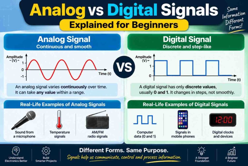
An analog signal is a continuous signal that can take on any value within a range, and it changes smoothly over time rather than jumping between fixed steps.
Think of a dimmer switch that can be turned to any position between fully off and fully bright, or a mercury thermometer where the reading rises and falls smoothly with temperature.
In electronics, an analog voltage might vary continuously between 0 and 5 volts, representing anything from the exact brightness of a room to the exact temperature read by a thermistor. This continuous nature is what makes analog signals a natural fit for representing real-world physical quantities.
What a Digital Signal Is
A digital signal, in contrast, only takes on a limited number of discrete values, most commonly just two: high and low, often represented as 1 and 0, or roughly 5 volts and 0 volts in many microcontroller systems.
There is no smooth transition between values in the way information is interpreted; a digital signal is either one state or another. This makes digital signals far more resistant to noise and interference, since a receiving circuit only has to decide whether a signal is closer to “high” or “low” rather than trying to preserve an exact continuous value.
Key Differences Side by Side
| Characteristic | Analog Signal | Digital Signal |
|---|---|---|
| Value range | Continuous, infinite possible values | Discrete, fixed set of values |
| Noise resistance | Lower, prone to distortion | Higher, easier to recover accurately |
| Processing | Requires analog circuitry or ADC | Directly readable by digital logic |
| Storage and transmission | More difficult to store precisely | Easy to store and transmit as data |
| Common examples | Sound waves, temperature readings, light intensity | Computer data, on/off switches, digital communication |
How Microcontrollers Bridge the Two Worlds
The physical world is fundamentally analog: temperature, sound, light, and pressure all vary continuously. But microcontrollers and computers process information digitally.
The bridge between these two worlds is the analog-to-digital converter, commonly abbreviated ADC, which is a circuit built into most modern microcontrollers. An ADC samples an analog voltage at regular intervals and converts each sample into a digital number that represents its approximate value.
This is exactly what happens when an Arduino reads a value from its analog pins connected to a sensor discussed in our sensors article; the analog voltage from the sensor is converted into a digital number the microcontroller’s code can work with.
Why the Distinction Matters for Wiring and Programming
Understanding whether a signal is analog or digital directly affects how you wire and code a project. Digital signals connect to digital input or output pins and are read or written as simple high or low states in code.
Analog signals connect to dedicated analog pins, and the microcontroller’s ADC converts the reading into a numeric value, often scaled to a range like 0 to 1023 on many common boards.
Getting this wrong, such as trying to read an analog sensor on a purely digital pin without an ADC, is a common beginner mistake that leads to confusing, unreliable readings during lab sessions and project demonstrations.
Practical Examples from Everyday Nigerian Electronics
Analog and digital signals both appear constantly in systems familiar to Nigerian students. A generator’s output voltage and current are inherently analog quantities that must be measured and converted before an automatic voltage regulator can process them digitally.
A solar charge controller reads an analog battery voltage, converts it digitally, and then generates a pulse width modulated output, a technique explained fully in our dedicated PWM article, to control charging. Meanwhile, a simple digital push-button interfaced to an Arduino is a clean example of a purely digital input, since it only ever reads as pressed or not pressed.
Converting Between Analog and Digital
Two key processes govern the relationship between analog and digital signals in practice.
- Analog-to-digital conversion (ADC) samples a continuous analog voltage and converts it into a digital number that a processor can store and manipulate.
- Digital-to-analog conversion (DAC) reverses the process, taking a digital number and producing a corresponding continuous analog voltage, useful for tasks like generating an audio waveform or a smooth control voltage.
Many low-cost microcontrollers lack a true DAC and instead approximate an analog-like output using pulse width modulation, switching a digital pin on and off rapidly enough that the average effect behaves similarly to a steady analog voltage.
Common Misconceptions
- “Digital signals are always better than analog signals.” Each has its place; analog signals are essential for representing continuously varying real-world quantities before they are converted, and many transducers naturally produce analog output.
- “An analog signal is just a ‘weaker’ or ‘noisier’ digital signal.” They are fundamentally different types of signals, not a strong and weak version of the same thing; the difference lies in whether values are continuous or discrete.
- “PWM output is a true analog signal.” PWM is actually a digital signal switching rapidly between on and off states; it only behaves like an analog signal after filtering or due to the averaging effect on a motor or LED.
Frequently Asked Questions
Why do microcontrollers need an ADC at all?
Microcontrollers process information in binary digital form, so an ADC is required to translate continuously varying real-world signals, such as sensor voltages, into digital numbers the processor can actually work with.
Is sound an analog or digital signal?
Sound in the physical world is an analog wave, but it is commonly converted to digital form for storage and processing in devices like phones and computers, then converted back to analog for the speaker to reproduce.
Can a digital pin on Arduino read an analog sensor directly?
Not accurately; a digital pin can only detect high or low states, so analog sensors should be connected to the board’s dedicated analog input pins to get a meaningful continuous reading.
Final Thoughts
Analog and digital signals represent two different ways of describing information, and nearly every embedded system relies on both at once, converting between them as needed.
Analog signals capture the smooth, continuous nature of real-world quantities, while digital signals offer the precision, noise resistance, and ease of processing that modern microcontrollers depend on.
Recognizing which type of signal you are working with, and knowing how to convert between them using an ADC or DAC, is a foundational skill that underpins sensor interfacing, PWM control, and much of embedded systems design covered throughout this site.