
If the diode taught you that current can be made to flow in only one direction, the transistor takes that idea a step further and turns it into something far more powerful: a tiny electronic switch and amplifier that underpins every microcontroller, computer processor, and digital circuit in existence.
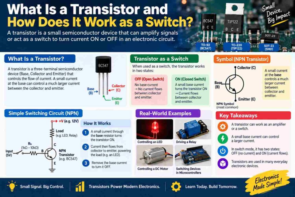
Understanding how a transistor works as a switch is one of the most important conceptual milestones in electronics education.
This article walks through what a transistor is, how it switches current on and off, and where it shows up in practical circuits.
What a Transistor Is
A transistor is a three-terminal semiconductor device capable of both amplifying electrical signals and acting as an electronic switch. The three terminals are typically called the base, collector, and emitter in a bipolar junction transistor, or gate, drain, and source in a field-effect transistor.
In switching applications, which are the most common use in digital and embedded systems work, a small signal applied to one terminal controls whether a much larger current is allowed to flow between the other two terminals, effectively turning the transistor into a switch controlled electronically rather than mechanically.
How a Bipolar Junction Transistor Works as a Switch
A bipolar junction transistor, or BJT, is built from three layers of semiconductor material, arranged as either NPN or PNP. In an NPN transistor, applying a small current to the base terminal allows a much larger current to flow from the collector to the emitter.
When no base current flows, the transistor is in cutoff and behaves like an open switch, blocking current between collector and emitter entirely.
When enough base current flows, the transistor enters saturation, behaving like a closed switch that allows current to flow freely. This small-current-controls-large-current relationship is the essence of transistor switching.
How a MOSFET Works as a Switch
A metal-oxide-semiconductor field-effect transistor, or MOSFET, achieves switching through a slightly different mechanism. Instead of a base current, a MOSFET is controlled by the voltage applied to its gate terminal. Below a certain gate voltage threshold, the MOSFET is off and current cannot flow between drain and source.
Above that threshold, a conductive channel forms, allowing current to flow freely between drain and source. Because MOSFETs are controlled by voltage rather than continuous current, they draw very little control power once switched, which makes them popular in efficient power switching applications, including motor drivers and PWM circuits discussed in our dedicated PWM article.
BJT vs MOSFET as a Switch: Quick Comparison
| Characteristic | BJT | MOSFET |
|---|---|---|
| Control method | Base current | Gate voltage |
| Control power needed | Higher, continuous current draw | Very low once switched |
| Switching speed | Moderate | Generally faster |
| Common use case | General-purpose switching, amplification | High-efficiency power switching, PWM circuits |
| Typical driving signal | Small base current via resistor | Gate voltage from a microcontroller pin or driver |
Why Transistors Are Essential for Microcontroller Circuits
A microcontroller pin can typically supply only a small amount of current, often just a few tens of milliamps, which is nowhere near enough to directly drive a motor, a relay coil, or a bright lighting load.
A transistor solves this problem by letting the microcontroller’s small output signal control a much larger current supplied from a separate power source.
This is exactly how most motor driver circuits, relay driver circuits, and high-power LED circuits in student and hobbyist projects are built, and it is a technique used constantly in Arduino-based projects, discussed further in our Arduino versus Raspberry Pi article.
Building a Basic Transistor Switch Circuit
A simple transistor switch circuit is one of the most common early exercises in electronics labs, and it demonstrates the switching principle clearly.
- Connect a current-limiting resistor between the microcontroller output pin and the transistor’s base terminal.
- Connect the transistor’s emitter to ground and the collector to the load, such as a small motor or relay coil.
- Connect the load’s other terminal to a separate supply voltage appropriate for the load, which may be higher than the microcontroller’s own supply.
- Add a flyback diode across an inductive load like a motor or relay coil to protect the transistor from voltage spikes when it switches off.
- Write code to set the control pin high and low, and observe the load switching on and off in response.
This same basic pattern, scaled up with appropriately rated components, is used in far more advanced industrial motor control and PLC output circuits, a topic covered in our PLC programming article.
Transistors Beyond Switching
While switching is the focus for most embedded systems and digital work, transistors are equally important as amplifiers in analog circuits, boosting weak signals such as those from a microphone or a sensor to usable levels.
The same basic device, biased differently, performs either function, which is part of why understanding transistor operation deeply pays off across both analog and digital electronics coursework.
Common Misconceptions
- “A transistor works exactly like a mechanical switch.” A transistor is controlled electronically by current or voltage rather than a physical movement, and it also has characteristics like voltage drop and switching speed that a simple mechanical switch does not.
- “BJTs and MOSFETs are interchangeable in every circuit.” They are controlled differently, current for BJTs and voltage for MOSFETs, so circuits must be designed around the specific type being used, and swapping one for the other without adjustment often causes the circuit to fail.
- “A microcontroller pin can safely drive any motor or relay directly.” Microcontroller pins can only supply small currents, so a transistor or similar driver circuit is almost always required to switch larger loads safely.
Frequently Asked Questions
Why is a flyback diode needed when a transistor switches an inductive load?
An inductive load like a motor or relay coil generates a sudden voltage spike when current through it is interrupted, and a flyback diode provides a safe path for that energy to dissipate, protecting the transistor from damage.
Can a single transistor control very high power devices directly?
A single transistor can control loads up to its rated current and voltage limits, but for very high power devices, engineers often use the transistor to drive a relay or a larger power transistor rather than switching the heavy load directly.
What is the difference between a transistor used as a switch and one used as an amplifier?
As a switch, a transistor is driven fully into cutoff or saturation to be either completely off or completely on, while as an amplifier, it operates in a linear region between these extremes to proportionally increase a signal’s strength.
Final Thoughts
The transistor’s ability to let a small signal control a much larger current makes it one of the most consequential inventions in electronics, forming the switching backbone of every digital circuit and microcontroller-based project you will build.
Whether working with a BJT controlled by base current or a MOSFET controlled by gate voltage, the underlying switching principle enables microcontrollers to safely control motors, relays, and lighting far beyond what their own pins could handle directly.
Mastering this concept early, through hands-on circuit building, pays dividends across nearly every embedded systems and power electronics topic you will encounter afterward.