
A transformer’s output voltage does not stay perfectly fixed as load changes, it sags slightly under heavier load due to internal impedance, and how much it sags is described by a specification called voltage regulation.
It is not the most talked-about transformer parameter, but it directly affects whether equipment downstream receives the voltage it needs across varying load conditions.
This article explains what transformer regulation means, how it is calculated, and why it matters in practical power system design.
What Voltage Regulation Actually Means
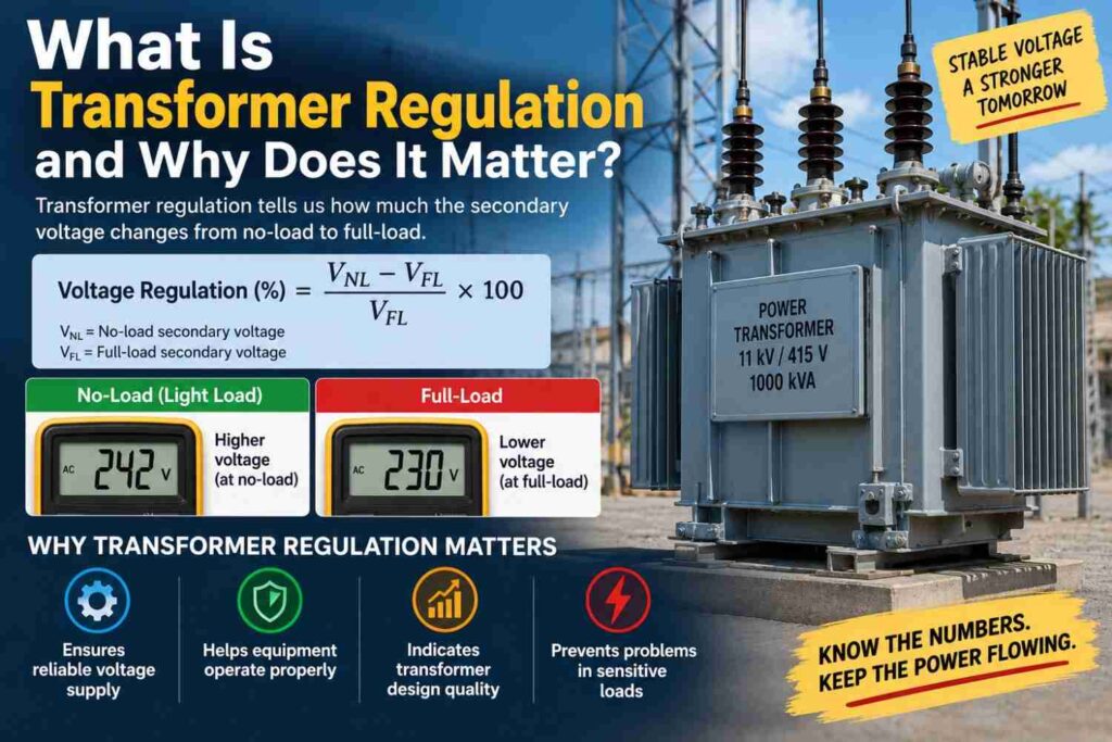
Transformer voltage regulation is the percentage change in secondary terminal voltage between no-load and full-load conditions, expressed relative to the rated secondary voltage. In simple terms, when a transformer is unloaded, its output voltage sits close to the ideal value predicted purely by the turns ratio, a relationship covered in our dedicated article on what a transformer is.
As load is applied, internal resistance and reactance in the windings cause a voltage drop, so the terminal voltage under full load is slightly lower than at no load. Regulation quantifies exactly how much that drop is.
The Regulation Formula
Voltage regulation is generally expressed as a percentage using the formula: Regulation (%) = ((No-load voltage minus Full-load voltage) divided by Full-load voltage) multiplied by 100. A transformer with 2 percent regulation, for example, means its output voltage at full load is about 2 percent lower than its output voltage at no load, assuming the primary supply voltage stays constant.
Lower regulation values indicate a transformer that holds its output voltage more steadily as load changes, which is generally the more desirable characteristic for most applications.
What Causes Voltage Regulation in the First Place
Regulation arises because every transformer winding has internal resistance and leakage reactance, together forming what is often summarised as the transformer’s internal impedance. As current flows through this impedance under load, it produces an internal voltage drop, similar in principle to how any real power source droops slightly under load. The size of this drop depends on both the magnitude of the load current and its power factor.
A load with a lagging power factor, common with inductive equipment like motors, typically produces worse regulation than a purely resistive load of the same magnitude, because the reactive component of current interacts with the transformer’s leakage reactance in a way that adds to the voltage drop.
Why Regulation Matters in Practice
Poor voltage regulation means connected equipment sees a wider swing in supply voltage as load varies throughout the day, which can affect the performance of sensitive electronic equipment, cause motors to run less efficiently, and in severe cases contribute to equipment damage from sustained undervoltage.
On a distribution network, transformers with poor regulation combined with long, heavily loaded feeders can leave customers at the far end of a line experiencing noticeably lower voltage during peak demand hours than customers closer to the source, a pattern familiar in many parts of the Nigerian distribution network where feeder lengths and loading are not always matched to transformer capacity.
Typical Regulation Values by Transformer Type
| Transformer Type | Typical Regulation Range | Notes |
|---|---|---|
| Small distribution transformer | 2% to 5% | Higher impedance design, lower cost |
| Large power transformer | 5% to 10% | Impedance often chosen partly for fault current limiting |
| Instrument transformers (CT/VT) | Very low, tightly specified | Accuracy prioritised over power handling |
How Engineers Manage Regulation in Design
Voltage regulation is not something to eliminate entirely, since some internal impedance is actually useful for limiting fault current during a short circuit, a topic connected to why transformers explode when internal faults go uncontrolled. Instead, engineers manage regulation through a combination of design and operational tools.
- Selecting transformer impedance values that balance fault current limiting against acceptable voltage droop
- Using on-load or off-load tap changers to adjust the turns ratio and compensate for regulation and supply voltage variation
- Improving load power factor through capacitor banks, which reduces the reactive component driving voltage drop
- Sizing conductors and feeder lengths to minimise additional voltage drop beyond the transformer itself
- Choosing parallel transformer operation for heavy loads, which can improve overall effective regulation compared to a single heavily loaded unit
Regulation vs Efficiency: Not the Same Thing
It is worth being clear that regulation and efficiency are related but distinct concepts. Efficiency describes how much of the input power is delivered as useful output versus lost as heat, tied closely to the loss mechanisms explained in our dedicated article on why transformers need cooling systems.
Regulation describes how much the output voltage itself changes with load, independent of how much power is lost as heat. A transformer can have excellent efficiency and still show noticeable voltage regulation, since regulation is driven by impedance and reactive effects rather than purely by resistive losses.
Practical Steps to Check and Improve Regulation
- Measure or obtain the transformer’s no-load and full-load secondary voltage from test data or nameplate information.
- Calculate the percentage regulation using the standard formula to establish a baseline.
- Check the load’s power factor, since correcting a poor power factor often improves effective regulation without any transformer changes.
- Confirm tap changer settings are appropriate for current supply voltage and load conditions.
- Evaluate feeder length and conductor sizing if downstream voltage remains unacceptable despite good transformer regulation.
Common Misconceptions
- “Zero voltage regulation would be ideal.” Some impedance is deliberately built in to limit fault current, so extremely low regulation is not automatically the design goal.
- “Regulation and efficiency are the same measurement.” Efficiency measures power loss as heat, while regulation measures how much output voltage changes with load; a transformer can score well on one and only moderately on the other.
- “Poor regulation always means a faulty transformer.” Regulation is a design characteristic tied to impedance and load power factor, not necessarily a sign of damage or malfunction.
Frequently Asked Questions
What is considered good voltage regulation for a distribution transformer?
Values in the range of 2 to 5 percent are typical and generally considered acceptable for most distribution-level applications.
Can voltage regulation be improved after a transformer is installed?
Yes, tap changer adjustments, power factor correction on the load side, and reducing feeder voltage drop can all improve the effective voltage seen by customers without replacing the transformer.
Does a lagging power factor really make regulation worse?
Yes, inductive loads with a lagging power factor typically produce a larger voltage drop across the transformer’s leakage reactance than an equivalent resistive load, worsening regulation.
Final Thoughts
Transformer regulation is a quiet but consequential specification, shaping how stable the voltage delivered to end users remains as load rises and falls through the day.
Understanding the balance between impedance, power factor, and practical tools like tap changers gives engineers a clearer way to manage voltage quality rather than treating it as an unavoidable side effect.
For a network like Nigeria’s, where load patterns and feeder conditions vary widely, keeping regulation in mind during both design and troubleshooting helps explain voltage complaints that might otherwise seem mysterious.