
Current transformers and voltage transformers are often mentioned in the same breath because both are instrument transformers that scale down high electrical quantities into safe, measurable signals, but they are built and wired in almost opposite ways.
Confusing the two, or wiring one the way you would wire the other, can damage equipment or endanger anyone working nearby. This article lays out exactly how current transformers and voltage transformers differ, and why that difference matters in practice.
What Each Device Actually Measures
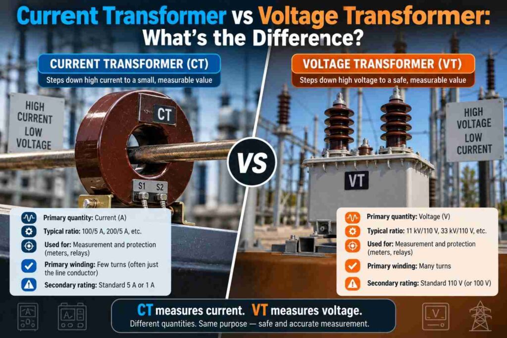
A current transformer, or CT, scales down a large current into a small, proportional secondary current, typically for use with ammeters, protection relays, and energy meters, a device covered in full detail in our dedicated article on what a current transformer is.
A voltage transformer, or VT, sometimes called a potential transformer, scales down a high voltage into a small, proportional secondary voltage, again for safe use with voltmeters, relays, and metering equipment. Both exist so that measurement and protection devices never need to be built to withstand the full primary voltage or current directly.
How They Are Connected Into the Circuit
This is where the two devices diverge sharply. A current transformer’s primary winding is connected in series with the circuit being measured, meaning the full load current passes directly through it. A voltage transformer’s primary winding is connected in parallel, or shunt, across the circuit, meaning it sees the full system voltage but draws only a small magnetising current. This wiring difference is the source of most of the practical hazards and handling rules that differ between the two devices.
Why the Secondary Circuit Rules Are Opposite
Because a CT’s primary is in series with the load current, the secondary current is essentially forced by whatever current flows in the primary, regardless of what is connected to the secondary.
If the CT secondary circuit is opened while the primary carries current, the entire primary ampere-turns must still be balanced, which forces the core into deep saturation and can generate dangerously high voltage spikes across the open terminals, a hazard explained fully in our dedicated article on why a current transformer secondary should never be left open.
A voltage transformer works the opposite way: because its primary is in parallel with the system voltage, the danger with a VT is short-circuiting its secondary, not opening it. A shorted VT secondary draws excessive current that can overheat and damage the winding, similar to shorting the secondary of any ordinary voltage source.
Side-by-Side Comparison
| Characteristic | Current Transformer (CT) | Voltage Transformer (VT) |
|---|---|---|
| Primary connection | Series with the circuit | Parallel (shunt) across the circuit |
| What it scales down | Current | Voltage |
| Typical secondary rating | 1 A or 5 A | 110 V or 100 V (phase or line, per standard) |
| Dangerous condition | Open-circuited secondary | Short-circuited secondary |
| Core loading | Determined by primary current, fixed | Determined by system voltage, largely fixed |
| Common uses | Metering, protection relays, ammeters | Metering, protection relays, voltmeters, synchronising |
Construction Differences
A CT is essentially designed to operate close to a short-circuited transformer, since its secondary normally feeds a low-impedance meter or relay coil, and its core is sized to avoid saturating under expected fault current for protection duty.
A VT, by contrast, is designed more like a small, precise power transformer operating close to open-circuit or light-load conditions, prioritising voltage ratio accuracy across a range of loading. These differing design goals mean the two devices are not interchangeable even at similar physical size or cost.
Where Each Is Used on the Nigerian Grid
Both device types appear throughout TCN transmission substations and DisCo distribution networks, though often for slightly different purposes. CTs are heavily used for revenue metering at customer connections and for protection relay inputs feeding differential and overcurrent schemes.
VTs are more commonly found at substation busbars and generator terminals, where accurate voltage sensing supports metering, automatic voltage regulation, and synchronising equipment before paralleling generators or interconnecting sections of the grid. On distribution feeders, VTs are somewhat less common than CTs simply because voltage measurement is needed less frequently than current measurement for everyday protection and billing purposes.
Practical Wiring and Safety Reminders
Field technicians working around instrument transformers benefit from a short mental checklist before disconnecting or servicing any metering or protection wiring:
- Confirm whether the circuit you are working on is a CT circuit or a VT circuit before touching any terminal.
- Never open a CT secondary circuit while the primary is energised; short it first using a shorting link or shorting switch if servicing is required.
- Never short-circuit a VT secondary; isolate it properly using its designated fuses or isolating links instead.
- Always verify correct polarity markings before connecting either device into a protection or metering scheme.
- Label CT and VT circuits clearly, since mixing up the two during maintenance is a common and entirely avoidable mistake.
Common Misconceptions
- “CTs and VTs are basically the same device used for different jobs.” They are built around opposite electrical principles, series connection with fixed current for CTs versus parallel connection with fixed voltage for VTs, which drives very different safety rules.
- “It’s safe to open either device’s secondary circuit if the equipment is switched off downstream.” A CT secondary must never be opened while primary current flows, regardless of what is or is not connected downstream.
- “VTs are less important than CTs because current is what trips protection.” Voltage sensing is essential for many protection functions, synchronising, and voltage regulation, and a faulty VT can be just as disruptive as a faulty CT.
Frequently Asked Questions
Can a CT be used in place of a VT, or vice versa?
No, their internal design, connection method, and safety characteristics are fundamentally different, and substituting one for the other would give inaccurate readings or create a hazard.
Why is a shorted CT secondary considered safe while a shorted VT secondary is not?
A CT is designed to operate essentially short-circuited under normal conditions since its secondary always feeds a low-impedance load, while a VT is designed to operate close to open-circuit, so forcing a short draws far more current than it is built for.
Do both CTs and VTs need to be periodically tested?
Yes, both should be checked for accuracy, insulation condition, and correct ratio periodically, particularly on revenue metering and protection circuits where errors have real financial or safety consequences.
Final Thoughts
Current transformers and voltage transformers solve a similar underlying problem, giving instruments and relays a safe, scaled-down signal to work with, but they arrive at that goal through opposite electrical arrangements.
Knowing which device you are dealing with, and respecting the very different safety rules that come with series versus parallel connection, is one of the more important practical distinctions any technician working around metering and protection panels needs to internalise.
Getting this wrong is not just a theoretical error, it is one of the more common causes of avoidable equipment damage and safety incidents in the field.