
Active power, reactive power and apparent power are three terms that trip up almost everyone encountering electrical engineering for the first time, mainly because all three are commonly just called “power” in casual conversation despite measuring genuinely different things. Once you see how they fit together, however, the confusion disappears almost immediately.
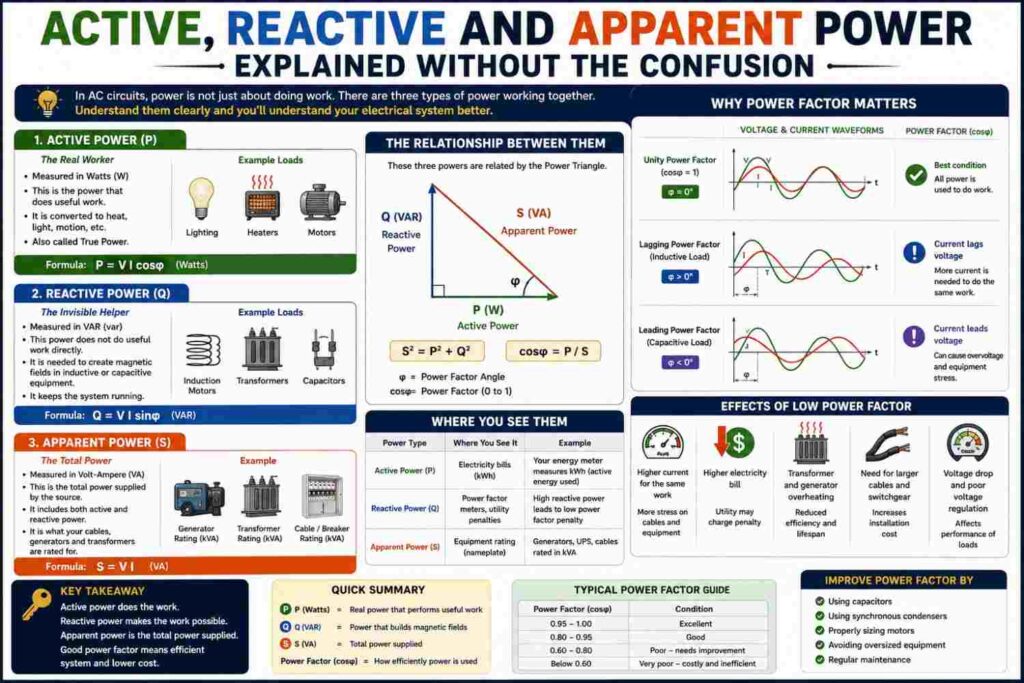
This article explains each one clearly, shows how they relate mathematically through the power triangle, and walks through everyday analogies and worked examples to make the ideas stick.
Why AC Power Needs Three Different Definitions
In a simple DC circuit, power is easy: multiply voltage by current, and you have your answer. But in AC (alternating current) circuits — which is what powers virtually every home, office and factory — things get more complicated whenever a circuit contains inductive components like motors, transformers or certain lighting ballasts. These components cause current to shift slightly out of step with voltage, and this timing shift is exactly what creates the need to separate power into active, reactive and apparent components.
Active Power (kW): The Power That Does Real Work
Active power, also called real power or true power, is measured in kilowatts (kW) and represents the power that actually performs useful work — spinning a motor shaft, producing light, generating heat, or running a compressor. This is the power that a standard energy meter bills you for, and it is what most people mean when they casually say “how much power does this appliance use.”
Active power is calculated as: P = V × I × cos(θ), where θ is the phase angle between voltage and current, and cos(θ) is the power factor discussed in our dedicated article on that topic.
Reactive Power (kVAR): The Power That Builds Magnetic Fields
Reactive power is measured in kilovolt-amperes reactive (kVAR) and represents power that oscillates back and forth between the source and the load without ever being consumed as useful work. It is required to establish and maintain the magnetic fields inside inductive components such as motor windings and transformer coils, or the electric fields inside capacitive components.
Reactive power is calculated as: Q = V × I × sin(θ). Although it does no useful work directly, reactive power is not “fake” or unnecessary — without it, motors and transformers simply could not function, since the magnetic fields it sustains are essential to how these devices convert electrical energy into mechanical or transformed electrical output.
Apparent Power (kVA): The Total Power the System Must Supply
Apparent power is measured in kilovolt-amperes (kVA) and represents the total combination of active and reactive power — effectively, the total power that a generator, transformer, inverter or utility connection actually has to be capable of delivering, and therefore the total current flowing through the system.
Apparent power is calculated as: S = V × I (without the power factor term), and relates to the other two through the Pythagorean-style formula: S² = P² + Q².
The Power Triangle
The clearest way to visualize how these three quantities relate is the power triangle, a right-angled triangle where:
- The horizontal side represents active power (P, in kW)
- The vertical side represents reactive power (Q, in kVAR)
- The hypotenuse (the longest side) represents apparent power (S, in kVA)
The angle between the horizontal side and the hypotenuse is θ, the same phase angle used in the power factor calculation. A smaller angle means reactive power is small relative to active power, giving a power factor close to 1.0. A larger angle means reactive power makes up a bigger share of the total, giving a lower power factor.
A Simple Analogy: The Glass of Beer
One of the most popular ways engineering instructors explain this trio is the “glass of beer” analogy. Imagine a mug of beer: the liquid beer itself represents active power — the part you actually wanted and can “drink” (use productively). The foam on top represents reactive power — it takes up space in the glass and was part of what was poured, but it is not something you can drink or use directly. The total volume of the full mug, beer plus foam together, represents apparent power — the total capacity the glass (your electrical system) had to accommodate, even though only part of it was truly useful.
A Worked Numerical Example
Suppose a motor draws 100A at 230V with a phase angle of 30° between voltage and current.
Apparent Power (S) = V × I = 230 × 100 = 23,000 VA = 23 kVA
Active Power (P) = S × cos(30°) = 23 × 0.866 = 19.9 kW
Reactive Power (Q) = S × sin(30°) = 23 × 0.5 = 11.5 kVAR
We can verify using the Pythagorean relationship: √(19.9² + 11.5²) = √(396 + 132.25) = √528.25 ≈ 23 kVA, confirming our apparent power figure.
Why This Distinction Matters in Practice
- Equipment sizing: Generators, transformers and inverters must be sized based on apparent power (kVA), since that represents the actual current they must be able to carry, not just the useful active power (kW) being delivered.
- Billing and penalties: Many commercial and industrial electricity tariffs bill based on kVA demand or apply penalties for poor power factor, directly tying reactive power to real financial cost.
- Cable and infrastructure sizing: Cables, switchgear and protection devices must handle the full current associated with apparent power, even though only the active power portion performs useful work.
Leading vs Lagging Reactive Power
Reactive power can be either “absorbed” or “supplied” depending on the type of load:
- Inductive loads (motors, transformers) absorb reactive power, causing current to lag behind voltage — a lagging power factor, the most common scenario in industrial settings.
- Capacitive loads (capacitor banks, some electronic equipment) supply reactive power, causing current to lead ahead of voltage — a leading power factor.
Power factor correction, discussed in depth in our dedicated power factor article, typically works by adding capacitive reactive power to offset the inductive reactive power absorbed by motors and transformers, bringing the overall reactive power — and therefore the power factor — closer to zero kVAR, or unity power factor.
Common Sources of Reactive Power in Real Systems
| Source | Type |
|---|---|
| Induction motors | Absorbs (lagging) |
| Transformers (especially lightly loaded) | Absorbs (lagging) |
| Fluorescent lighting with magnetic ballast | Absorbs (lagging) |
| Capacitor banks | Supplies (leading) |
| Long unloaded transmission cables | Supplies (leading) |
Measuring Active, Reactive and Apparent Power in Practice
Modern power quality analyzers and many digital energy meters can measure all three quantities simultaneously by sampling the instantaneous voltage and current waveforms many times per second and calculating the phase relationship between them. Simpler clamp meters may show only current and, in some models, an estimated power factor, while dedicated three-phase power analyzers used by engineers can break down active, reactive and apparent power separately for each phase of a three-phase system, along with harmonic distortion and other power quality metrics. For facility managers investigating a suspected power factor problem, a temporary power quality survey using this kind of instrument, often left logging data for several days to capture varying load conditions, is the standard first step before deciding on the size of any corrective equipment.
How These Quantities Interact With Harmonics
The classical power triangle described above assumes clean, sinusoidal voltage and current waveforms. In real modern electrical systems, however, non-linear loads such as variable frequency drives, LED lighting drivers, computers and other electronic equipment distort the current waveform, introducing harmonics — additional frequency components beyond the fundamental 50Hz. These harmonics create an additional category sometimes called distortion power, which behaves somewhat like reactive power in that it increases total current and apparent power without contributing useful active power, but is not fully captured by the simple cos(θ) power factor calculation alone. In facilities with large numbers of electronic loads, engineers increasingly refer to “true power factor” (which accounts for harmonics) versus “displacement power factor” (the traditional cos(θ) value) to distinguish between these two related but distinct effects, and specialized harmonic filters, distinct from standard capacitor banks, may be needed to address harmonic-related issues specifically.
Three-Phase Considerations
Most of the calculations in this article are shown for a single-phase system for simplicity, but the same active, reactive and apparent power concepts apply directly to three-phase systems, which are common in industrial and larger commercial installations across Nigeria. In a balanced three-phase system, total power is simply three times the per-phase value, or can be calculated directly using P = √3 × Vline × Iline × cos(θ) for active power, with corresponding formulas for reactive and apparent power. Understanding three-phase power calculations is essential for anyone sizing industrial transformers, generators or motor control equipment, since miscalculating by forgetting the √3 factor is a common and consequential error for students and even some practicing technicians when first working with three-phase systems.
Common Misconceptions
- “Reactive power is wasted energy.” It is not consumed or “wasted” in the same sense as active power converted to heat losses, but it does occupy system capacity and contribute to current flow, which does cause real I²R losses in cables and equipment.
- “Apparent power and active power should always be equal.” They are only equal when power factor is exactly 1.0 (unity), which is rare in real inductive-load-heavy systems without correction.
- “Only industrial facilities need to worry about these distinctions.” While the financial and billing impact is mostly felt by larger commercial and industrial customers, the underlying physics applies to every AC circuit, including the inverter and generator systems used in ordinary homes.
How This Applies to Generators and Inverters in Nigerian Homes
This distinction directly explains a common source of confusion when sizing backup power equipment: a generator or inverter’s kVA rating (apparent power capacity) is not the same as the kW of useful appliances it can actually run, because some of that kVA capacity is consumed by reactive power, especially when running motor-heavy loads like air conditioners, pumps, refrigerators and washing machines simultaneously. A “5kVA” generator, at a typical 0.8 power factor, realistically delivers only around 4kW of active power for actual appliance use, which is precisely why generators and inverters can seem to “struggle” or trip even when the connected appliances’ rated wattages appear to add up to less than the generator’s kVA rating on paper.
A Quick Reference Summary
Because these three terms are so easily confused, it helps to have a single, condensed reference: active power (kW) is the power that does useful work and is what you pay for on a standard meter; reactive power (kVAR) is the power that sustains magnetic fields in motors and transformers without doing useful work itself, but still occupies system capacity; and apparent power (kVA) is the total combination of both, representing the true current-carrying burden placed on generators, transformers, cables and inverters. Whenever you see equipment rated in kVA rather than kW, remember that the usable kW figure will always be somewhat lower, depending on the power factor of the connected load, which is exactly why understanding this trio matters well beyond the classroom.
Frequently Asked Questions
Which of the three power types does my prepaid meter measure?
Standard residential prepaid meters measure active power (kWh), not apparent or reactive power, which is why power factor rarely affects typical household bills directly.
Can reactive power exist without any active power?
In theory, a purely reactive load (like an ideal capacitor or inductor with no resistance) would draw only reactive power with zero active power, though in practice virtually all real components have some resistance and therefore consume at least some active power.
Why is reactive power measured in kVAR instead of kW?
Using a different unit (kVAR) helps clearly distinguish reactive power from active power (kW) and apparent power (kVA) in calculations and equipment ratings, even though all three share the same fundamental dimensional units of volts times amps.
Does reactive power cause my generator to burn more fuel?
Indirectly, yes. While reactive power itself performs no useful work, supplying it still requires the generator to carry additional current, which increases losses and can push the generator toward a less efficient operating point, particularly if the generator is already running close to its kVA capacity.
Is apparent power always larger than active power?
Yes, except in the special case of a perfect unity power factor (1.0), where they are exactly equal. In all other cases, apparent power is always greater than or equal to active power, since it also accounts for reactive power.
How can I reduce the reactive power my home or business draws?
For most homes, reactive power is not significant enough to warrant action. For businesses with heavy motor loads, installing appropriately sized capacitor banks, as discussed in our power factor article, is the standard solution for reducing reactive power drawn from the supply.
Why do some inverters list both a kVA rating and a separate kW rating?
This is done specifically to help buyers understand both figures at once: kVA indicates the maximum apparent power (and therefore maximum current) the inverter can handle, while the kW rating, usually calculated at a stated power factor such as 0.8, indicates the realistic maximum active power available for actually running appliances, which is the more directly useful number for everyday planning.
Do reactive power problems ever affect voltage stability?
Yes. Reactive power flow is closely linked to voltage levels across a power system; excessive reactive power demand, especially over long distribution lines, can contribute to voltage drop, while excessive reactive power supply (from over-correction) can contribute to overvoltage, which is why grid operators actively manage reactive power balance across the network, not just active power generation.
Final Thoughts
Active, reactive and apparent power describe three genuinely different aspects of how AC electrical systems behave, and understanding the distinction between them clears up a huge amount of confusion around equipment sizing, electricity billing, and why backup power systems sometimes underperform their advertised ratings. Whether you remember it through the power triangle, the glass-of-beer analogy, or simply the formulas themselves, grasping these three power types is one of the most useful foundational skills in all of electrical engineering. It is a concept that rewards revisiting: the first time through, the formulas and the triangle may feel abstract, but the moment you connect it to a real generator struggling under a motor-heavy load, or a factory bill carrying an unexpected penalty charge, the whole picture tends to click into place at once. Keep the power triangle in mind, and the next time someone mentions kVA, kW or kVAR in the same sentence, you will know exactly how they relate and why the distinction was worth defining in the first place.