
Series and parallel circuits are two of the very first concepts taught in any electrical engineering course, yet the difference between them explains a huge amount of everyday electrical behavior; from why your house wiring is designed the way it is, to why old-style Christmas lights would all go dark if a single bulb blew, to how your car battery is connected to its many electrical systems.
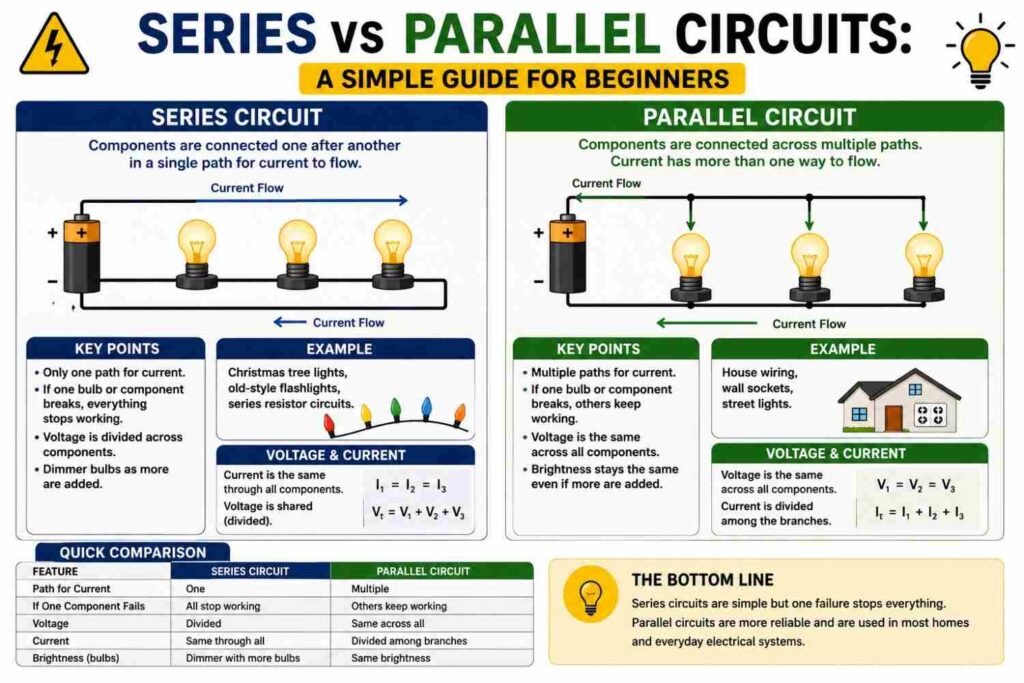
This guide breaks both circuit types down from first principles, with clear diagram-free explanations, worked calculations, and real-world examples anyone can relate to.
What Is a Series Circuit?
In a series circuit, components are connected one after another, forming a single continuous path for current to flow. There is only one route the current can take, meaning the same current flows through every component in the circuit, one after another, with no branching.
Because there is only one path, if that path is broken anywhere — a blown bulb, a disconnected wire, an open switch — current stops flowing through the entire circuit. This is exactly why old-style decorative light strings, wired in series, would go completely dark if even a single bulb failed: the broken bulb interrupted the only available path for current.
What Is a Parallel Circuit?
In a parallel circuit, components are connected across common points, creating multiple independent paths for current to flow. Each component has its own separate branch, and current can take any or all of these branches simultaneously, dividing between them based on each branch’s resistance.
Because each branch is independent, if one component fails or is disconnected, current can still flow through the other branches unaffected. This is exactly why turning off one light in your house does not affect any other light or appliance — each is wired on its own independent parallel branch.
How Voltage Behaves in Series vs Parallel
- Series circuits: The total supply voltage divides across each component according to its resistance. Components with higher resistance take a larger share of the total voltage.
- Parallel circuits: Every branch receives the same full supply voltage, regardless of how many branches there are or what their individual resistances are.
How Current Behaves in Series vs Parallel
- Series circuits: The same current flows through every component, since there is only one path available for it to take.
- Parallel circuits: Total current from the source divides among the branches, with more current flowing through lower-resistance branches and less through higher-resistance ones.
How Resistance Combines
The formulas for total resistance differ significantly between the two configurations:
Series total resistance: Rtotal = R1 + R2 + R3 + …
Parallel total resistance: 1/Rtotal = 1/R1 + 1/R2 + 1/R3 + …
An important consequence of the parallel formula is that total resistance in a parallel circuit is always less than the smallest individual resistance in the circuit — adding more parallel branches always decreases total resistance and increases total current drawn from the source, which is why adding more appliances to a parallel household circuit increases the load on that circuit.
A Worked Example: Series Circuit
Suppose three resistors of 10Ω, 20Ω and 30Ω are connected in series to a 60V supply.
Total resistance = 10 + 20 + 30 = 60Ω
Total current (Ohm’s Law) = 60V ÷ 60Ω = 1A
Since the same 1A flows through every resistor, the voltage across each can be found using V = I × R: 10V across the first resistor, 20V across the second, and 30V across the third — together adding back up to the full 60V supply.
A Worked Example: Parallel Circuit
Now suppose the same three resistors (10Ω, 20Ω, 30Ω) are connected in parallel to a 60V supply instead.
1/Rtotal = 1/10 + 1/20 + 1/30 = 0.1 + 0.05 + 0.033 = 0.183
Rtotal ≈ 5.46Ω
Each branch receives the full 60V, so current through each can be found individually: 6A through the 10Ω branch, 3A through the 20Ω branch, and 2A through the 30Ω branch, for a total of 11A drawn from the source — far more than the 1A drawn in the series example, illustrating how dramatically the configuration changes overall circuit behavior even with identical components.
Why Household Wiring Uses Parallel Circuits
Household electrical wiring is designed almost entirely as parallel circuits, for very practical reasons:
- Independent operation: Every socket and light needs to work independently. If your home were wired in series, turning off one appliance would cut power to every other appliance on the same circuit.
- Consistent voltage: Every appliance needs the full 230V supply to work correctly, not a fraction of it divided among other connected devices, which is exactly what parallel wiring provides.
- Fault isolation: If one appliance or fixture fails, or its individual fuse/breaker trips, the rest of the circuit continues operating normally.
The related but distinct concept of radial versus ring circuit wiring, covered in our dedicated wiring guide, describes different ways of physically arranging these parallel branches within a home’s wiring layout.
Where Series Circuits Are Still Used
Despite parallel circuits dominating household wiring, series circuits remain useful and common in specific applications:
- Battery packs: Cells are often connected in series to add up their voltages, such as four 1.5V cells in series producing a combined 6V.
- Fuses and circuit breakers: These are deliberately placed in series with a circuit so that they can interrupt the entire current path when a fault is detected.
- Certain LED strip designs and current-regulated lighting: Some LED configurations use series wiring within small groups, deliberately relying on a single controlled current path.
- Some older sensor and control circuits: Simple safety interlock circuits, such as an emergency stop loop across multiple machines, are sometimes deliberately wired in series so that any one triggered stop breaks the entire loop.
Series-Parallel (Combination) Circuits
Many real-world electrical systems are not purely series or purely parallel, but a combination of both, often called series-parallel or combination circuits. For example, a battery bank might have groups of cells connected in series to reach a target voltage, with multiple such series strings then connected in parallel to increase total capacity — a configuration commonly used in inverter and solar battery banks, discussed further in our dedicated article on 12V vs 24V vs 48V inverter systems. Analyzing these combination circuits requires breaking them down step by step, simplifying series sections and parallel sections separately before combining the results.
Comparing Series and Parallel Circuits
| Feature | Series Circuit | Parallel Circuit |
|---|---|---|
| Number of current paths | One | Multiple |
| Current through each component | Same throughout | Divides by branch |
| Voltage across each component | Divides by resistance | Same across each branch |
| Effect of one component failing | Entire circuit stops | Other branches unaffected |
| Total resistance | Sum of all resistances | Less than smallest resistance |
| Typical household use | Rare (mainly protection devices) | Standard for sockets and lighting |
Power Dissipation in Series vs Parallel Circuits
Power dissipated by each resistive component can be calculated using P = I²R or P = V²/R, and the results differ meaningfully between the two configurations even for identical components. In our series example, the 30Ω resistor, carrying the same 1A as the others but with the highest resistance, dissipates the most power (P = 1² × 30 = 30W) despite having the same current as the others, because power scales with resistance when current is fixed. In our parallel example, the 10Ω resistor, carrying the highest current of the three branches, actually dissipates the most power (P = 60² ÷ 10 = 360W) because power scales inversely with resistance when voltage is fixed. This is a useful illustration of why simply knowing a component’s resistance is not enough to predict its power dissipation without also knowing whether it sits in a series or parallel arrangement relative to the rest of the circuit.
Troubleshooting Tip: Using Circuit Type to Find Faults
Understanding series versus parallel behavior is also a genuinely practical troubleshooting skill. If an entire string of lights or a full circuit loses power all at once, and you know it is wired in series, the fault is likely a single broken connection somewhere along that one shared path, and a multimeter set to continuity or voltage mode can be used to test each segment in turn to isolate exactly where the break has occurred. If, on the other hand, only one specific appliance or fixture has stopped working while everything else on the same circuit continues operating normally, this points strongly toward a parallel wiring arrangement with an isolated fault, such as a blown bulb, a faulty appliance, or a problem specific to that one branch, rather than a fault affecting the shared supply itself.
Common Misconceptions
- “Parallel circuits are always safer than series circuits.” Safety depends on proper design, protection devices and installation quality, not simply on circuit topology; both configurations are safe when correctly engineered for their intended purpose.
- “More parallel branches always mean more available power.” Adding parallel branches increases total current drawn from the source, which must still be within the safe capacity of the supply, wiring and protection devices; parallel wiring does not create additional power on its own.
- “Series circuits are obsolete and never used anymore.” While rare in household power wiring, series configurations remain essential in battery design, protection devices and specific control and lighting applications.
A Simple Way to Remember the Difference
Many students find it helpful to picture a single-lane road versus a multi-lane highway. A series circuit is like a single-lane road: every car (electron) must pass through the same single route, one after another, and a single stalled car (broken component) blocks the entire road for everyone behind it. A parallel circuit is like a multi-lane highway: cars can spread out across several independent lanes, and a stalled car in one lane does not block traffic in the other lanes at all. This mental image maps directly onto the electrical behavior described throughout this article: shared single-path current in series, and independent multi-path current in parallel.
How This Applies to Solar and Inverter Battery Banks
Series and parallel wiring choices are especially important when designing solar panel arrays and inverter battery banks, both common in Nigerian homes and businesses seeking backup power. Connecting solar panels in series increases the combined voltage while keeping current the same as a single panel, whereas connecting them in parallel increases combined current while keeping voltage the same — a distinction covered in full detail in our dedicated article on series versus parallel solar panel connections. Battery banks follow the same logic: connecting batteries in series raises the system voltage (useful for reaching 24V or 48V inverter systems), while connecting battery strings in parallel increases total energy storage capacity at a fixed voltage. Getting this wrong, such as mixing batteries of different ages or capacities within a series string, can lead to poor performance or even damage, which is why professional installation matters for larger backup power systems. Mixing batteries of different ages, brands or states of charge within the same series string is one of the most common installation mistakes seen in the field, since the weakest cell in a series string is forced to work as hard as the strongest ones, leading to premature failure, reduced total usable capacity, and in some cases overheating or safety hazards. Reputable solar and inverter installers always match batteries carefully by type, age and capacity when building series-parallel battery banks for exactly this reason, and replacing only one battery in an aging bank, rather than the full set, is generally discouraged for the same reason.
Frequently Asked Questions
Why did old Christmas lights all go out when one bulb failed?
Because they were wired in series, meaning there was only one path for current; a single failed bulb broke that path entirely, stopping current everywhere in the string.
Why don’t modern LED light strings have this problem?
Most modern LED strings are wired with parallel groups, or include bypass mechanisms, specifically so that one failed LED does not disable the entire string.
Is household wiring ever partly series?
The protection devices themselves, such as circuit breakers and fuses, are wired in series with their respective circuits so they can interrupt current when needed, even though the sockets and appliances downstream are wired in parallel with each other.
Which configuration draws more current from the supply, series or parallel?
For the same set of components, a parallel configuration almost always draws more total current from the supply than a series configuration, because parallel wiring reduces total resistance while series wiring increases it.
How do I know if two components are in series or parallel just by looking at a circuit?
If current has only one possible path through both components with no branching point between them, they are in series. If there is a branching point where current can choose to flow through either component independently before rejoining, they are in parallel.
Can a circuit be neither purely series nor purely parallel?
Yes, this is very common in real-world electronics and power systems, and is called a series-parallel or combination circuit, requiring the circuit to be broken down into smaller series and parallel sections for analysis.
Why do some appliance manuals warn against connecting devices “in series” with an extension cord?
Because household appliances are designed to receive the full supply voltage directly across their terminals, as they would in a parallel connection. Placing a device in series with another load would cause the supply voltage to divide between them unpredictably, likely resulting in reduced performance, malfunction, or damage.
Does wiring type (series or parallel) affect energy efficiency?
Not directly by itself; efficiency depends more on the resistance and design of the components involved. However, poor circuit design choices, such as unnecessarily high resistance in a series path, can contribute to wasted energy as heat, which is why proper cable sizing and connection quality matter regardless of configuration.
Final Thoughts
Understanding the difference between series and parallel circuits unlocks an intuitive grasp of an enormous range of electrical systems, from why your household sockets all work independently, to how battery banks are configured for solar and inverter systems, to why a single blown fuse can take down an entire circuit while a single blown light bulb in your living room does not. Once the core distinction, one path versus multiple paths, and how voltage and current behave differently in each, becomes second nature, a great deal of everyday electrical design starts to make much more intuitive sense. It is a small piece of foundational knowledge that pays off repeatedly, whether you are studying for an engineering exam, wiring a new extension in your home, or simply trying to understand why one faulty bulb took down an entire string of lights while another time it did not.