
Step-up and step-down transformers do exactly what their names suggest: one increases voltage, and the other decreases it. But beyond that simple definition lies a genuinely important set of engineering decisions about where each type is used, why the grid needs both, and what happens if the wrong one is ever used in the wrong place.
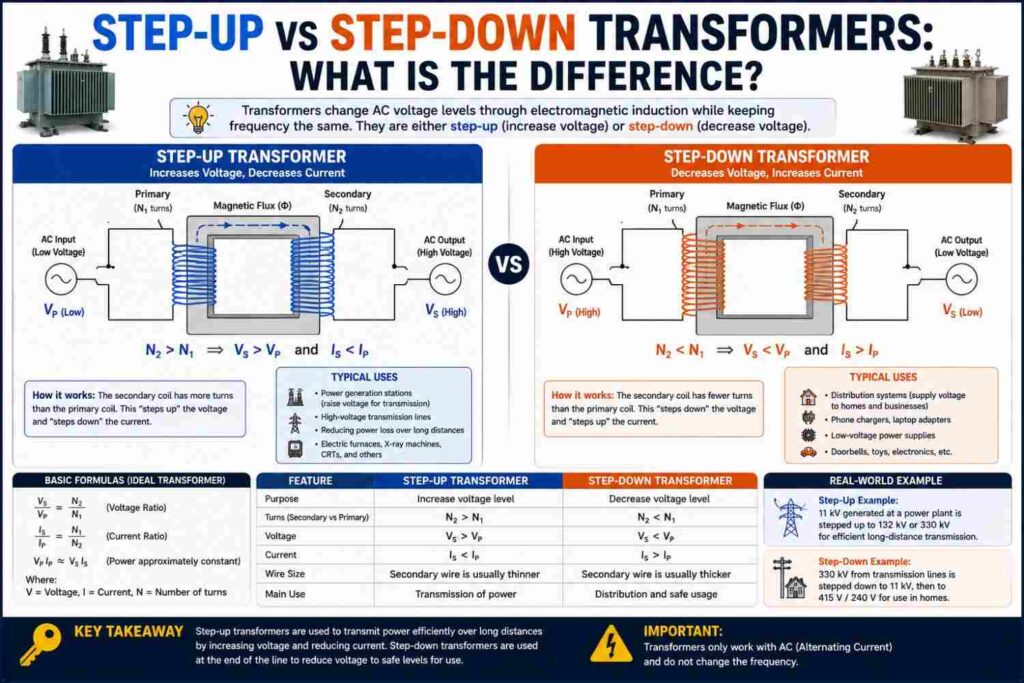
This article breaks down the difference in detail, with real examples from how electricity actually travels from a power station to your home.
The Basic Definition
Both step-up and step-down transformers work on exactly the same underlying principle described in our main article on how transformers work: two coils sharing a magnetic core, with voltage determined by the ratio of turns between the primary and secondary windings. The only difference is which direction the voltage changes:
- Step-up transformer: The secondary winding has more turns than the primary winding, so output voltage is higher than input voltage. Current is correspondingly reduced on the output side.
- Step-down transformer: The secondary winding has fewer turns than the primary winding, so output voltage is lower than input voltage. Current is correspondingly increased on the output side.
Physically, many transformers can actually function as either type depending on which winding is used as the input, though in practice most are designed, installed and protected for one specific direction of use.
Why Step-Up Transformers Exist
Step-up transformers are used primarily at power generating stations. A generator might produce electricity at somewhere between 11kV and 25kV, which is far too low a voltage to transmit efficiently over long distances, since transmission losses (I²R losses) increase dramatically as current increases for a given amount of power. A step-up transformer raises this generated voltage to transmission-level voltages, commonly 132kV, 330kV or higher, which allows the same amount of power to be transmitted with much lower current, and therefore much lower losses, across the sometimes hundreds of kilometers between a power station and the cities it serves.
Why Step-Down Transformers Exist
Step-down transformers reverse this process at the receiving end. High transmission voltages like 330kV or 132kV are far too dangerous and impractical to bring directly into a city, let alone into a home. A series of step-down transformers progressively reduces this voltage in stages:
- Transmission voltage (132kV–330kV) is stepped down at a major substation to sub-transmission or distribution voltage (33kV or 11kV).
- This is further stepped down at local distribution transformers, often the pole-mounted or ground-mounted units seen in neighborhoods, to the final 230V/400V level used directly by homes and businesses.
Without this staged step-down process, delivering electricity safely to household sockets would be essentially impossible.
A Side-by-Side Comparison
| Feature | Step-Up Transformer | Step-Down Transformer |
|---|---|---|
| Voltage change | Increases | Decreases |
| Current change | Decreases | Increases |
| Secondary vs primary turns | More turns on secondary | Fewer turns on secondary |
| Typical location | Power generating stations | Substations, neighborhoods, appliances |
| Primary purpose | Efficient long-distance transmission | Safe, usable voltage for end users |
A Worked Example of Each
Step-up example: A generator produces 11kV. A step-up transformer with a turns ratio designed to achieve a 30:1 increase would output approximately 330kV for transmission: 11kV × 30 = 330kV.
Step-down example: A distribution transformer receives 11kV from a local feeder. With a turns ratio designed to step this down by roughly 48:1, the output would be approximately 229V, close to Nigeria’s standard household voltage: 11,000V ÷ 48 ≈ 229V.
Everyday Examples You Already Own
Step-down transformers are not limited to grid infrastructure — they exist inside many household devices too:
- Laptop and phone charger “bricks” typically step 230V down to a much lower DC-suitable AC voltage before further conversion to DC.
- Doorbell transformers step household voltage down to a low, safe voltage (often 12V or 24V) for the doorbell circuit.
- Older CRT televisions and some audio amplifiers used internal step-up transformers to generate higher voltages needed for specific internal components.
Step-up transformers, by contrast, are much less common in everyday consumer devices and are mostly found in generation, industrial and specialized equipment contexts, precisely because most household and office devices need lower voltages than the mains supply, not higher ones.
Why Not Just Use One Transformer for the Whole Journey?
A natural question is why the grid uses multiple transformers in stages, rather than one large step-up unit and one large step-down unit. The answer comes down to practicality and safety at each stage: distribution networks need to branch out to serve many different areas and customers at manageable voltage levels, and having intermediate stepping stages (transmission → sub-transmission → distribution → utilization voltage) allows the network to be designed, protected and maintained in manageable, standardized sections, with appropriately sized equipment and safety margins at each level rather than one enormous, unwieldy conversion.
What Happens If a Transformer Is Wired Backwards?
Because a transformer’s step-up or step-down behavior depends only on which winding is used as the input, connecting a step-down transformer “backwards” would actually make it behave as a step-up transformer, and vice versa — but this is not simply a curiosity to experiment with. Transformers are designed with insulation, core saturation limits and protection equipment matched to their intended direction and voltage levels. Deliberately reversing a transformer without proper engineering assessment can cause insulation breakdown, core saturation, excessive current draw, or dangerous overvoltage on the “wrong” side, and should never be attempted outside a controlled, professionally supervised setting.
Step-Up and Step-Down Transformers in Nigeria’s Grid
Nigeria’s national grid follows this same staged structure: power stations such as those at Egbin, Kainji, Jebba, Shiroro and others generate electricity at relatively low voltage, which is then stepped up for transmission across the country’s 330kV and 132kV backbone network managed by the Transmission Company of Nigeria (TCN). At the receiving end, DisCos operate step-down substations and local distribution transformers that bring this down to the familiar 230V/400V level used in homes and businesses nationwide. Faults, overloads or maintenance issues at any of these transformer stages, from a major substation down to a single street transformer, are a common underlying cause of localized outages, even when generation and transmission elsewhere on the grid are functioning normally.
Insulation and Design Differences Between the Two Types
Although step-up and step-down transformers share the same fundamental operating principle, their engineering design often differs in important ways because of the voltage levels involved at each winding:
- Insulation requirements: A step-up transformer’s secondary winding, carrying the higher voltage, requires significantly more robust insulation than its primary winding. Engineers must carefully account for this asymmetry when designing winding layers, spacing and insulation materials.
- Core saturation limits: The core must be designed to handle the flux levels associated with the transformer’s intended operating direction without saturating, which would distort the output waveform and increase losses.
- Tap changers: Many step-down distribution and substation transformers include tap changers, allowing small adjustments to the turns ratio to compensate for variations in incoming supply voltage, helping maintain a more stable output voltage for customers despite fluctuations elsewhere on the grid.
Choosing the Right Transformer Type for a Project
For engineers and technicians involved in electrical installation or industrial projects, selecting between step-up and step-down configurations (or specifying a transformer’s turns ratio more generally) depends on a clear understanding of both the source voltage available and the required voltage at the point of use. Key questions typically include:
- What is the voltage of the available supply (the primary side)?
- What voltage does the connected equipment or downstream network actually require (the secondary side)?
- What is the expected load in kVA, including reasonable headroom for future growth?
- What environmental and safety standards apply, including insulation class, cooling method and protection requirements?
Getting any of these wrong, particularly voltage direction, can result in equipment damage, safety hazards, or a transformer that simply cannot serve its intended purpose, which is why transformer specification is typically handled by a qualified electrical engineer rather than treated as an off-the-shelf purchasing decision.
Losses at Each Transformation Stage
Every time voltage passes through a transformer, whether stepping up or down, a small amount of energy is lost as heat due to core and copper losses, discussed in more depth in our main transformer article. On a typical journey from power station to home, electricity might pass through three or four separate transformers: a step-up unit at generation, a step-down unit at a major substation, possibly an intermediate step-down at a secondary substation, and a final step-down distribution transformer near the point of use. While each individual transformer is highly efficient, these losses accumulate across the full journey, which is one of several reasons overall grid losses (combined with transmission line losses, which are also significant) mean that considerably more electricity must be generated than is ultimately metered and billed to end customers. Utilities and grid operators continuously work to minimize these cumulative losses through better equipment, more efficient designs and optimized network planning, since even small efficiency improvements at scale translate into meaningful fuel and capacity savings across an entire national grid.
How Utilities Decide Where to Place Step-Down Transformers
Distribution engineers do not place local step-down transformers randomly; placement is planned around expected load density, geographic coverage and voltage drop limits. A transformer placed too far from the customers it serves, or serving too many customers relative to its rating, can result in noticeably lower voltage at the far end of its service area during peak demand periods, sometimes called voltage drop or “brown-out” conditions, where appliances receive less than their rated voltage and may run inefficiently or struggle to start. This is one reason planned network expansion, including adding new transformers as an area grows, is an ongoing and necessary part of utility operations, and why some rapidly developing neighborhoods experience more voltage-related issues than more established ones with mature, well-planned distribution infrastructure.
Common Misconceptions
- “Step-up transformers create extra energy.” They do not; they only trade voltage for current, keeping total power (minus small losses) essentially constant.
- “A step-down transformer is less efficient than a step-up transformer.” Efficiency depends on design quality and load conditions, not on the direction of voltage change; both types can be built to very high efficiency.
- “Any transformer can safely be used in either direction.” While physically possible in principle, using a transformer outside its designed direction and rating without proper engineering review risks damage or dangerous failure.
Real-World Scale: From Power Station to Pocket
To appreciate just how much voltage transformation actually happens on the journey from generation to a household device, consider a typical path: a generator produces power at roughly 11kV, a step-up transformer raises this to 330kV for cross-country transmission, a substation step-down transformer reduces it to 33kV, a secondary substation may step it down further to 11kV, and a final local distribution transformer brings it down to 230V at your wall socket. If you then plug in a phone charger, an internal step-down stage inside the charger reduces this further still, typically to 5V or less, before final conversion to DC. In total, a single unit of energy reaching your phone may have passed through five or more distinct voltage transformation stages, each one a step-up or step-down transformer doing precisely the job described in this article, quietly and invisibly, every single day.
Frequently Asked Questions
Which type of transformer is more common?
Step-down transformers are far more numerous overall, since every neighborhood, building and many individual devices need one, whereas step-up transformers are comparatively few, concentrated mainly at generating stations and select industrial applications.
Do step-up and step-down transformers look different?
Not necessarily from the outside; the physical construction can look similar, and the step-up or step-down behavior is determined by the internal winding design and turns ratio, not by any visibly distinguishing external feature.
Can the same transformer be used for both stepping up and stepping down at different times?
In principle, yes, since the behavior depends on which side is used as input, but in practice transformers are engineered, insulated and protected for a specific intended direction and should not be repurposed without professional assessment.
Why does the grid need so many stages of step-down transformers instead of just one big one?
Staged step-down allows the network to branch safely into smaller distribution areas at each voltage level, using appropriately sized and protected equipment, rather than attempting one impractically large voltage conversion in a single step.
What happens if a step-down transformer is overloaded?
It can overheat, experience accelerated insulation aging, or trip its protection equipment, potentially causing a localized outage until the fault is cleared or the transformer is repaired or replaced — a common practical cause of neighborhood power interruptions.
Is a voltage stabilizer the same as a step-down transformer?
Not quite; a voltage stabilizer typically uses a variable-ratio (often auto-transformer-based) design that actively adjusts its output to compensate for fluctuating input voltage, whereas a standard step-down transformer has a fixed ratio and fixed voltage relationship.
Why do power stations not just generate electricity at the final transmission voltage directly, skipping the step-up transformer?
Generating electricity directly at hundreds of thousands of volts would require extraordinarily bulky and expensive generator insulation and construction. It is far more practical and economical to generate at a moderate voltage (matched to generator design constraints) and then use a dedicated step-up transformer, which is a comparatively simpler and more cost-effective piece of equipment, to reach transmission-level voltages.
Do solar inverters use step-up or step-down transformers?
It depends on the system. Some solar inverter designs use a step-up transformer stage internally to raise the DC or low-AC voltage from the panels to grid-compatible AC voltage, while many modern transformerless inverters achieve voltage conversion electronically without a traditional transformer at all, relying instead on power electronic switching circuits.
Final Thoughts
Step-up and step-down transformers are two sides of the same coin, both essential to making a national electricity grid work at all. Step-up transformers make long-distance transmission efficient, while step-down transformers make the resulting high voltage safe and usable at the point of consumption. Together, they form the invisible backbone of the journey every unit of electricity takes from a distant power station to the socket you plug your phone charger into every day.
Whether you are an engineering student learning the underlying theory for the first time, a technician troubleshooting a local distribution fault, or simply a curious homeowner wondering what happens between the power station and your wall socket, understanding this one distinction unlocks a clear, practical picture of how the entire electricity grid is structured from end to end.
It is a concept worth carrying with you the next time you flip a switch: behind that simple action lies a carefully engineered chain of step-up and step-down stages, each one quietly doing its job so that the power reaching you is both efficient to deliver and safe to use.