
Transformers are everywhere in the electrical world, yet they are one of the most misunderstood pieces of equipment among non-engineers. You have almost certainly seen one without realizing it: the grey drum-shaped equipment mounted on a pole near your street, the humming metal box inside an electrical substation, or even the small block on your laptop charger.
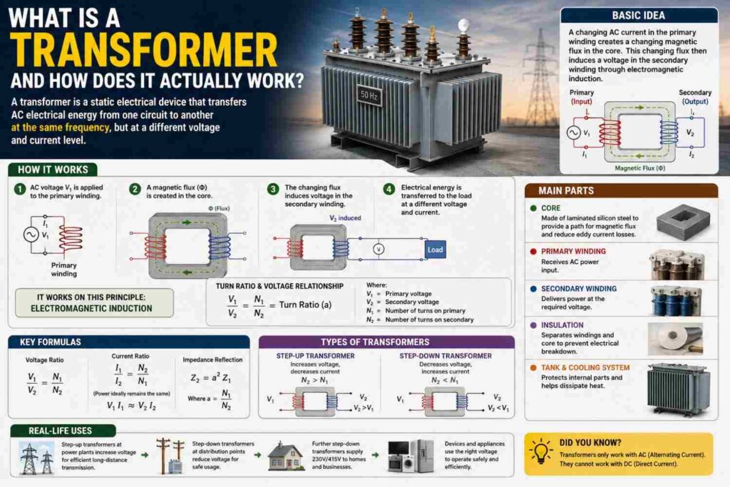
This article explains what a transformer actually is, how it works using nothing more exotic than magnetism, why it is so central to how electricity reaches your home, and what commonly goes wrong with them.
What Is a Transformer?
A transformer is a static (no moving parts) electrical device that transfers electrical energy from one circuit to another, while changing the voltage level in the process. Transformers can “step up” voltage (increase it) or “step down” voltage (decrease it), which is why you will often hear the terms step-up transformer and step-down transformer, covered in detail in our dedicated comparison article.
Critically, a transformer does not generate power — it only converts the relationship between voltage and current for a given amount of power, and it only works with AC (alternating current), not DC.
How a Transformer Actually Works
At its core, a transformer consists of two coils of wire, called windings, wound around a shared iron core, but electrically isolated from each other:
- Primary winding: The coil connected to the incoming power source.
- Secondary winding: The coil connected to the outgoing load or circuit.
Here is the step-by-step process of how energy transfers between them:
- Alternating current flows into the primary winding, and because the current is constantly changing direction (50 times per second on a 50Hz system), it creates a constantly changing magnetic field around the primary coil.
- This changing magnetic field is channeled through the iron core, which is specifically designed to efficiently carry and concentrate magnetic flux.
- The changing magnetic field passes through the secondary winding, and by a principle called electromagnetic induction (discovered by Michael Faraday), this changing field induces a voltage in the secondary winding — without any direct electrical (wired) connection between the two coils.
- The magnitude of the induced voltage depends on the ratio of the number of turns of wire in each coil, known as the turns ratio.
The Turns Ratio Formula
The relationship between the primary and secondary voltage is governed by a simple formula:
Vsecondary ÷ Vprimary = Nsecondary ÷ Nprimary
Where N represents the number of turns of wire in each winding. If the secondary winding has more turns than the primary, the transformer steps voltage up. If it has fewer turns, the transformer steps voltage down.
A Worked Example
Suppose a transformer has 1,000 turns on its primary winding and 100 turns on its secondary winding, and it is connected to a 230V supply:
Vsecondary = Vprimary × (Nsecondary ÷ Nprimary) = 230 × (100 ÷ 1000) = 23V
This transformer steps 230V down to 23V — a 10:1 step-down ratio, similar in principle to the kind of transformer that might be used inside low-voltage equipment or control systems.
What Happens to Current?
Because a transformer (ideally) neither creates nor destroys power, the power going into the primary winding must equal the power coming out of the secondary winding (minus small losses). Since P = V × I, this means that whenever voltage is stepped down, current is stepped up proportionally, and vice versa. In the example above, if the secondary winding delivers 10A at 23V, the primary winding would only need to draw about 1A at 230V to supply the same 230VA of power (ignoring minor losses).
Why Transformers Are Essential to the Power Grid
Transformers appear at almost every stage of the journey electricity takes from a power station to your home:
- At the power station: Step-up transformers raise the generator’s output voltage to very high transmission voltages (132kV, 330kV and beyond), because transmitting at high voltage dramatically reduces energy losses over long distances, as explained in our dedicated article on why electricity is transmitted at high voltage.
- At substations: Step-down transformers reduce transmission voltage to distribution-level voltages, typically in the range of 11kV to 33kV.
- On your street: A final distribution transformer (often the pole-mounted or ground-mounted unit you may have seen) steps this down further to the 230V/400V level used directly in homes and businesses.
Without transformers at each of these stages, it would be essentially impossible to transmit electricity efficiently over long distances while still delivering it safely at usable household voltages. In effect, every unit of electricity you use at home has typically passed through three or more transformers on its journey from the generating station, each one adjusting the voltage-to-current relationship to suit the requirements of that particular stage of the grid, from bulk long-distance transmission down to the low-voltage wiring inside your walls.
Types of Transformers
| Type | Common Use |
|---|---|
| Power transformer | Substations, bulk power transmission |
| Distribution transformer | Stepping down to household/business voltage |
| Isolation transformer | Electrical isolation for safety or sensitive equipment |
| Auto-transformer | Voltage stabilizers, some AVR systems |
| Instrument transformer | Metering and protection systems |
Why Transformers Hum
The humming sound you may have heard near a distribution transformer is caused by a phenomenon called magnetostriction, where the iron core physically expands and contracts very slightly as the magnetic field alternates, vibrating at a frequency related to the supply frequency. This is normal for a healthy transformer under load; however, a sudden change in humming volume or pitch, or a new rattling or buzzing sound, can indicate a developing fault and may be worth reporting to your DisCo, a topic covered further in our dedicated article on why distribution transformers hum.
Common Transformer Losses
No transformer is perfectly efficient. The main sources of loss include:
- Copper losses (I²R losses): Resistive heating in the winding wires, which increase with load current.
- Core losses (iron losses): Energy lost to hysteresis and eddy currents within the iron core, which occur even when the transformer is unloaded.
- Stray losses: Smaller losses due to leakage flux and other secondary effects.
Well-designed modern transformers are highly efficient, often exceeding 95-98% efficiency at rated load, but losses still generate heat, which is why larger transformers are fitted with cooling fins, oil-filled tanks, or fans.
Single-Phase vs Three-Phase Transformers
Transformers can be built for single-phase or three-phase systems, and the choice depends on the application:
- Single-phase transformers are typically used for smaller loads, such as individual homes or small businesses on lightly loaded streets, and are generally simpler and less expensive.
- Three-phase transformers are used for larger loads, such as industrial facilities, large commercial buildings, or bulk distribution feeding many customers, because three-phase power delivers a more constant, efficient power flow and allows for smaller conductor sizes relative to the power delivered. A three-phase transformer can be built as a single unit with three sets of windings on a shared core, or as a bank of three separate single-phase transformers connected together.
Nigerian distribution networks make extensive use of both types, with three-phase transformers typically feeding larger clusters of customers or industrial areas, and smaller single-phase transformers sometimes serving lighter residential loads directly.
Transformer Cooling Methods
Because transformer losses generate heat, larger units require deliberate cooling systems to stay within safe operating temperatures. Common cooling methods, often abbreviated with standardized codes, include:
- ONAN (Oil Natural, Air Natural): The transformer’s oil circulates naturally by convection, and heat is dissipated to the surrounding air naturally, without fans or pumps — common in typical distribution transformers.
- ONAF (Oil Natural, Air Forced): Fans are added to force air across the radiators, improving cooling capacity for the same transformer size, often used when a transformer needs to handle higher loads than its natural cooling rating allows.
- OFAF/OFWF (Oil Forced): Pumps actively circulate oil, sometimes combined with water cooling, used in very large power transformers at major substations and power stations.
How to Read a Transformer Nameplate
Every transformer carries a nameplate with key information useful for engineers, technicians and even curious homeowners:
- Rated power (kVA or MVA): The maximum apparent power the transformer is designed to handle continuously.
- Primary and secondary voltage: The designed input and output voltage levels.
- Frequency (Hz): The AC frequency the transformer is designed for — 50Hz in Nigeria and most of the world outside the Americas.
- Impedance percentage: A value used by engineers to calculate fault current levels and coordinate protection equipment.
- Vector group: Describes how the windings are internally connected (such as Dyn11), important for three-phase transformers operating in parallel with others.
Maintaining and Protecting Transformers
Because transformers are expensive, long-lived assets that are difficult to replace quickly, proper maintenance and protection are taken seriously by utilities and industrial facility managers alike. Common protective measures include:
- Overcurrent and differential protection relays that quickly disconnect a faulty transformer before internal damage escalates.
- Buchholz relays on oil-filled transformers, which detect gas buildup caused by internal arcing or overheating faults.
- Regular oil sampling and dissolved gas analysis (DGA) to detect developing internal problems before they cause a failure.
- Surge arresters to protect against lightning strikes and switching surges that could otherwise damage winding insulation.
What Happens When Your Local Distribution Transformer Fails
For many Nigerian communities, the local distribution transformer is a shared, critical piece of infrastructure serving an entire street or neighborhood, and its failure is often felt immediately and collectively. Common triggers for a local transformer failure or trip include severe overloading (especially during periods of high collective demand, such as when many households simultaneously run air conditioners), lightning strikes, vandalism or theft of transformer oil and components, and simple old age combined with deferred maintenance. Because a single transformer often serves dozens or hundreds of customers, its failure can mean an entire community loses grid power until the DisCo repairs or replaces it, which is part of why community-level generator and inverter backup systems remain so common. Some residential areas and estates have pooled resources to fund transformer upgrades or replacements directly with their DisCo in order to speed up this process, since utility repair timelines can vary considerably depending on parts availability and logistics.
Transformer Ratings and Choosing Backup Power
Understanding transformer capacity is also useful context when thinking about generator or inverter sizing for a shared facility, such as an estate or commercial plaza. Just as a distribution transformer has a kVA rating that limits how much load it can safely serve, a backup generator or inverter has its own kVA or kW rating with the same fundamental limitation: exceeding it risks tripping, overheating, or premature equipment failure. This shared underlying logic, of matching a power source’s rated capacity to the actual connected load, applies equally whether you are an engineer sizing a substation transformer or a homeowner sizing a backup inverter.
Common Misconceptions About Transformers
- “A transformer can convert DC to a different voltage.” Transformers only work with AC, because they rely on a constantly changing magnetic field. DC-to-DC voltage conversion requires entirely different technology, such as a DC-DC converter.
- “A bigger transformer is always better.” Oversizing a transformer relative to its actual load leads to it running at a poor efficiency point and can contribute to power factor issues; transformers should be sized to match expected load, with reasonable headroom for growth.
- “Transformers create electrical energy.” They only convert the voltage/current relationship of existing power; they cannot generate new energy, and in fact always consume a small amount of energy themselves as losses.
Frequently Asked Questions
Can a transformer work with a battery or other DC source?
Not directly. Since transformers rely on a changing magnetic field, a steady DC supply produces no induction in the secondary winding at all once the initial surge passes. This is why DC systems use different voltage conversion technology.
Why do some transformers have oil inside them?
Larger transformers are often filled with mineral oil, which serves as both an insulator and a cooling medium, helping dissipate the heat generated by core and copper losses far more effectively than air alone.
What causes a transformer to fail?
Common causes include prolonged overloading, insulation breakdown over time, moisture ingress, lightning strikes and surges, and manufacturing defects — explored in more depth in our dedicated article on why transformers explode.
Is a transformer the same thing as a voltage stabilizer?
Not exactly. A basic transformer has a fixed turns ratio and therefore a fixed voltage relationship, while a voltage stabilizer (often built using an auto-transformer with tap-changing) actively adjusts its ratio to compensate for fluctuating input voltage and maintain a steady output.
Why does my street sometimes lose power while a nearby street doesn’t?
Often because different streets are fed from different distribution transformers or feeders, so a fault, overload or maintenance issue affecting one transformer will not necessarily affect a neighboring one supplied from a different source, a topic explored further in our dedicated article on this exact phenomenon.
How efficient is a typical distribution transformer?
Modern distribution transformers commonly achieve efficiencies in the 95-98% range at their rated load, though efficiency drops somewhat at very light or very heavy loading compared to their optimal design point.
Why do transformers need to be grounded (earthed)?
Earthing a transformer’s neutral point and casing provides a safe reference point for the electrical system and a low-resistance path for fault current to flow if internal insulation fails, helping protection devices detect and clear faults quickly rather than leaving dangerous voltages present on exposed metal parts.
Can a transformer be used to change AC frequency, such as from 50Hz to 60Hz?
No. A standard transformer only changes voltage level; it does not change frequency, since it simply follows whatever frequency is present in the incoming AC waveform. Changing frequency requires different equipment, such as a frequency converter or a motor-generator set.
Why do some transformers get replaced with a larger one over time?
As a neighborhood or facility’s electricity demand grows, whether through new buildings, more air conditioners, or added machinery, the original transformer may no longer have enough spare capacity to serve peak demand safely, prompting the DisCo or facility owner to upgrade to a higher-kVA unit rather than risk chronic overloading and premature failure.
Final Thoughts
Transformers may look like simple, unglamorous grey boxes, but they are one of the most important inventions in the history of electrical engineering, making the entire modern grid possible by allowing electricity to be transmitted efficiently over long distances and then safely stepped down for everyday use. Understanding how they work through electromagnetic induction and the turns ratio formula demystifies not just the transformer itself, but a large part of how electricity gets from a power station to the socket in your wall. The next time you notice that quiet hum coming from a green metal box on your street, you will know exactly what is happening inside it, and why it matters to your own power supply.