
Voltage, current, resistance and power are the four building blocks of everything electrical, from the smallest LED bulb to the largest industrial motor. Yet many people who use electricity every single day; flipping switches, charging phones, running generators; have never had these four terms explained in plain language.
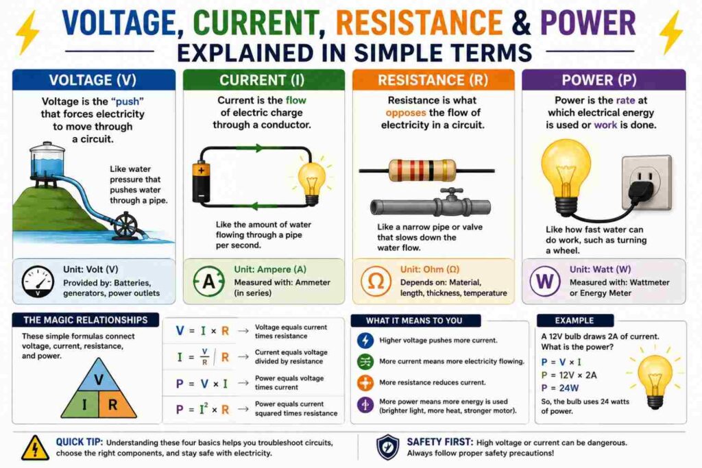
This guide breaks each one down using simple analogies, shows how they relate to each other through Ohm’s Law and the power formula, and walks through practical, real-world examples so the concepts actually stick.
The Water Pipe Analogy
The most common and effective way to understand electricity is to compare it to water flowing through a pipe:
- Voltage is like water pressure — the force pushing water (or electric charge) through the system.
- Current is like the flow rate — how much water (or charge) is actually moving past a point per second.
- Resistance is like the narrowness of the pipe — anything that restricts or opposes the flow.
- Power is like the overall “work” the flowing water can do — for example, how forcefully it can turn a water wheel, which depends on both the pressure and the flow rate together.
Keep this analogy in mind as we define each term more precisely below.
What Is Voltage?
Voltage, measured in volts (V), is the electrical “pressure” or potential difference that pushes electric charge through a circuit. It is the force that makes current want to flow. Nigeria’s standard household supply is nominally 230V single-phase (with 400V available between phases in three-phase supplies), which is the “pressure” pushing current through your home’s wiring whenever a circuit is completed.
Without voltage, there is no driving force, and no current will flow, no matter how good a conductor is available. A battery, a generator, an inverter, or the national grid all serve as sources of voltage.
What Is Current?
Current, measured in amperes or “amps” (A), is the actual rate of flow of electric charge through a conductor. It tells you how much charge is passing a given point in the circuit every second. Current is what actually does the work inside a device — it is the moving charge that heats a filament, spins a motor, or powers a microchip.
Current only flows when there is both a voltage source and a complete, closed circuit path for it to travel through. This is why a broken wire, an open switch, or a blown fuse stops current instantly, even though voltage may technically still be present at the source.
What Is Resistance?
Resistance, measured in ohms (Ω), is the opposition a material offers to the flow of current. Every material has some resistance, though it varies enormously: metals like copper and aluminum have very low resistance (which is why they are used for wiring), while materials like rubber and plastic have extremely high resistance (which is why they are used for insulation).
Resistance is also why wires and components heat up when current flows through them — some electrical energy is converted to heat as current pushes through the material’s opposition, an effect engineers call I²R loss.
What Is Power?
Power, measured in watts (W), describes the rate at which electrical energy is converted into another form — light, heat, motion or sound. Power is what ultimately determines how “strong” an electrical effect is: a 100W bulb produces more light and heat than a 5W bulb, and a 2000W kettle heats water far faster than a 500W one.
Ohm’s Law: The Relationship Between Voltage, Current and Resistance
These three quantities are tied together by one of the most fundamental equations in all of electrical engineering, known as Ohm’s Law:
V = I × R
Where V is voltage (volts), I is current (amps), and R is resistance (ohms). This can be rearranged depending on what you are solving for:
- I = V ÷ R (current equals voltage divided by resistance)
- R = V ÷ I (resistance equals voltage divided by current)
In plain terms: for a fixed resistance, increasing voltage increases current proportionally. For a fixed voltage, increasing resistance decreases current. This single relationship explains an enormous range of everyday electrical behavior.
The Power Formula
Power relates to voltage and current through another simple formula:
P = V × I
Where P is power (watts). Combined with Ohm’s Law, this can also be rewritten as P = I² × R or P = V² ÷ R, depending on which quantities are known. These variations are extremely useful for engineers calculating heat losses in cables (using I²R) or comparing power delivered at different voltage levels.
A Worked Example
Suppose you have a heating element with a resistance of 20Ω, connected to a 230V supply. Using Ohm’s Law:
I = V ÷ R = 230 ÷ 20 = 11.5A
Now using the power formula:
P = V × I = 230 × 11.5 = 2,645W (about 2.6kW)
This tells us the heating element draws 11.5 amps and consumes about 2.6kW of power — useful information for choosing the correct circuit breaker rating and cable size for that circuit.
Why These Four Quantities Matter in Everyday Life
1. Choosing the Right Cable and Breaker
Cables and circuit breakers are rated by the current (amps) they can safely carry. Understanding how voltage, resistance and power relate to current is essential for selecting cables and breakers that will not overheat or trip unnecessarily.
2. Understanding Why Appliances Behave Differently
A high-resistance appliance like an incandescent bulb draws relatively little current, while a low-resistance appliance like a kettle’s heating element draws a great deal of current at the same voltage — explaining why kettles need dedicated, heavier-duty wiring.
3. Diagnosing Electrical Faults
Many electrical faults, including short circuits and overloads, can be understood directly through these relationships: a short circuit is essentially resistance collapsing toward zero, which (by Ohm’s Law) causes current to spike dramatically for the same voltage, tripping breakers or causing damage.
How to Measure Voltage, Current and Resistance With a Multimeter
A basic digital multimeter is one of the most useful tools for putting these concepts into practice, and most models handle all three measurements:
- Measuring voltage: Set the multimeter to the appropriate AC or DC voltage range, then place the probes across (in parallel with) the two points you want to measure — for example, across a wall socket’s live and neutral terminals. Never attempt this on exposed mains wiring without proper training and safety precautions.
- Measuring current: Set the multimeter to the current range, and connect it in series within the circuit, meaning the circuit must be broken and the meter inserted into the path so all current flows through it. This is more involved than voltage measurement and is why many technicians prefer a clamp meter, which measures current without breaking the circuit at all, by detecting the magnetic field around a conductor.
- Measuring resistance: Set the multimeter to the resistance (ohms) range, and always measure resistance on a component that is disconnected from any power source, since attempting to measure resistance on a live circuit can damage the meter and produce inaccurate readings.
Learning to make these three measurements confidently is one of the most practical entry points into hands-on electrical work, whether for a student, a hobbyist, or a homeowner trying to diagnose a simple fault before calling a professional electrician.
Typical Voltage Levels You’ll Encounter
| System | Typical Voltage |
|---|---|
| AA/AAA battery | 1.5V |
| Car battery | 12V |
| USB charging | 5V |
| Nigerian household socket (single-phase) | ~230V |
| Three-phase supply (phase-to-phase) | ~400V |
| Distribution lines | 11kV–33kV |
| Transmission lines | 132kV–330kV |
Series vs Parallel: How Resistance Combines
How resistance, current and voltage behave depends heavily on whether components are connected in series or in parallel — a topic covered in full detail in our dedicated article on series versus parallel circuits, but worth touching on briefly here:
- In series circuits, the same current flows through every component, while voltage divides across each one according to its resistance. Total resistance is the simple sum of all individual resistances (Rtotal = R1 + R2 + R3…).
- In parallel circuits, the same voltage appears across every branch, while current divides between branches according to each branch’s resistance. Total resistance is always less than the smallest individual resistance, calculated using 1/Rtotal = 1/R1 + 1/R2 + 1/R3…
Household wiring is predominantly parallel: every socket and light fixture receives the same 230V, and each draws its own independent current based on what is plugged in, which is exactly why turning on one appliance does not dim or affect others on a properly designed circuit.
Why Power Is Lost as Heat in Wires (I²R Losses)
Every real conductor has some resistance, however small, which means some energy is always converted to heat as current flows — a loss engineers calculate using Ploss = I² × R. This formula reveals something important: power loss increases with the square of current, not just proportionally. Doubling the current through a wire quadruples the heat generated, which is precisely why undersized cables carrying more current than they were designed for can heat up dramatically and become fire hazards, and why cable sizing (covered in our dedicated wiring guide) is such a safety-critical calculation rather than a mere cost consideration.
This same formula is also why electricity is transmitted across long distances at very high voltages: for a fixed amount of power delivered (P = V × I), raising voltage allows current to be proportionally reduced, which shrinks I²R losses dramatically over the many kilometers of transmission line between a power station and your city.
AC vs DC: Does Ohm’s Law Still Apply?
Ohm’s Law and the basic power formula were originally developed for DC (direct current) circuits, where voltage and current are steady and do not change direction. Nigeria’s grid, generators and most household supply are AC (alternating current), where voltage and current continuously oscillate direction, typically 50 times per second (50Hz). For simple resistive loads like incandescent bulbs and heating elements, Ohm’s Law still applies directly using the RMS (root-mean-square) values of voltage and current. For loads containing coils or capacitors, such as motors and transformers, the concept of impedance (a more general form of resistance that accounts for AC effects) is needed, along with the concept of power factor, to fully describe the relationship between voltage, current and power.
Earthing, Resistance and Why It Matters for Safety
Resistance is not just about how conductors behave — it is central to how earthing (grounding) protects people from electric shock. A proper earth connection provides a low-resistance path for fault current to flow safely to the ground instead of through a person who happens to touch a faulty appliance. When earthing resistance is too high (due to poor connections, corrosion, or an inadequate earthing rod), fault current may not flow strongly enough to trip a circuit breaker quickly, leaving a dangerous voltage present on the appliance’s casing for longer than it should be. This is one of the many practical reasons a solid understanding of resistance is not just theoretical, but directly tied to electrical safety in every home and workplace.
Common Misconceptions
- “High voltage always means more dangerous current.” Not necessarily — danger depends on the current that can actually flow through a person’s body, which depends on both voltage and the resistance of the path, including skin resistance and grounding conditions.
- “Amps and watts are the same thing.” They are related but different units; watts (power) equal volts multiplied by amps, not amps alone.
- “A thicker wire always carries more voltage.” Wire thickness relates to current-carrying capacity (ampacity) and resistance, not voltage. Voltage is determined by the source, not the wire.
How This Applies to Nigerian Homes and Generators
Because Nigeria’s grid, generators and inverters commonly supply a nominal 230V single-phase, the current draw of any appliance can be estimated directly from its wattage using I = P ÷ V. This is precisely how electricians determine whether a particular combination of appliances will overload a circuit, a generator, or an inverter: by adding up the total wattage of everything running at once, dividing by 230V to get total current, and comparing that against the rated capacity of the breaker, generator or inverter in question.
Frequently Asked Questions
What is the easiest way to remember Ohm’s Law?
Many students use a triangle with V at the top and I and R at the bottom; covering the quantity you want to find reveals the correct formula (V = I×R, I = V/R, or R = V/I).
Does resistance change with temperature?
Yes, for most conductors, resistance increases as temperature increases, which is one reason overloaded, overheating wires become progressively more dangerous — rising resistance generates even more heat, compounding the problem.
Why do some appliances draw more current at the same voltage?
Because they have lower internal resistance or higher power ratings. Ohm’s Law and the power formula together explain why: for a fixed voltage, lower resistance means higher current, and higher power means higher current.
Is DC electricity different from AC in terms of these formulas?
Ohm’s Law and the basic power formula apply to both, though AC circuits with inductive or capacitive components require additional concepts like impedance and power factor, covered in our dedicated article on power factor.
How do engineers measure these quantities in practice?
Voltage is measured with a voltmeter, current with an ammeter or clamp meter, and resistance with an ohmmeter; a modern multimeter typically combines all three functions in one handheld device.
Why does my generator or inverter specify both kVA and voltage?
Because current-carrying capacity, and therefore how many appliances can be run simultaneously, depends on both the power rating and the supply voltage, following the same P = V×I relationship covered in this article.
Can voltage be present without any current flowing?
Yes. Voltage can exist across an open switch or a disconnected appliance with no current flowing at all, since current requires a complete circuit. This is why a live wire can still be dangerous even when nothing appears to be “on” — voltage is present and current will flow the instant a path is completed, including through a person who touches it.
Why do some appliances specify a voltage range instead of a single value, such as “220–240V”?
Manufacturers design equipment to tolerate normal fluctuations in supply voltage that occur in real grids, including the Nigerian grid, where voltage can vary somewhat around its nominal 230V value depending on load conditions, distance from the transformer, and overall grid stability.
Final Thoughts
Voltage, current, resistance and power are not abstract academic concepts; they are the practical foundation behind every decision about cable sizing, breaker selection, appliance safety and backup power sizing. Once the water-pipe analogy and the two core formulas, Ohm’s Law and the power formula, become second nature, a huge amount of everyday electrical behavior stops being mysterious and starts making intuitive sense.
For anyone pursuing electrical engineering as a field of study or a career, these four quantities and the two formulas connecting them will keep resurfacing in every subsequent topic, from motor design to power system analysis, which is exactly why they are always taught first.