
If you have ever looked at an electricity bill from a factory or a large commercial building in Nigeria and noticed a separate line item or penalty charge related to “power factor,” you are not alone in wondering what it actually means.
Power factor is one of those electrical engineering terms that sounds intimidating but is, in reality, a simple and measurable idea once it is broken down piece by piece. It quietly affects everything from how efficiently your factory’s motors run, to how large a generator or transformer you need, to how much you end up paying the Distribution Company (DisCo) every month.
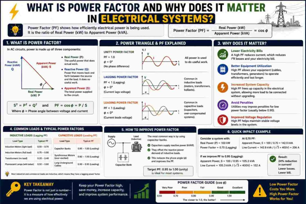
In this article, we will explain what power factor really is, why it exists in the first place, how it is calculated, what a “good” power factor looks like, what causes it to go wrong, and what can be done to correct it. By the end, you should understand why electrical engineers, facility managers and even DisCos care so much about this single number.
What Is Power Factor?
Power factor is a ratio that describes how effectively electrical power supplied to a system is being converted into useful work output. It is expressed as a number between 0 and 1, or equivalently as a percentage between 0% and 100%. A power factor of 1.0 (or 100%) means that all of the power supplied by the utility, generator or inverter is being used efficiently to do real work. A power factor of 0.5, on the other hand, means that only half of the supplied power is doing useful work, while the rest is essentially oscillating back and forth in the system without ever performing a real task.
Mathematically, power factor is defined as:
Power Factor (PF) = Real Power (kW) ÷ Apparent Power (kVA)
To fully understand this formula, you need to understand the three related quantities that describe power in any AC (alternating current) electrical system: real power, reactive power, and apparent power.
Real Power, Reactive Power and Apparent Power
Every AC electrical circuit that contains motors, transformers, fluorescent or older-style lighting ballasts, or any other device built around coils and magnetic fields (collectively called inductive loads) deals with three related quantities:
- Real Power (measured in kW): This is the actual power that performs useful work — turning a motor shaft, producing light, generating heat, or running a compressor. This is the power you are ultimately paying for in terms of usable output, and it is what a standard prepaid or postpaid energy meter is designed to record.
- Reactive Power (measured in kVAR): This is power that oscillates back and forth between the source and the load without performing any useful work on its own. It is needed to establish and maintain the magnetic fields inside motors, transformers and other inductive devices, but it does not directly produce mechanical or thermal output.
- Apparent Power (measured in kVA): This is the vector combination of real power and reactive power, and it represents the total power that the utility, generator or inverter actually has to be capable of supplying, and therefore the total current that has to flow through the wires, cables, switchgear and transformers.
These three quantities are commonly visualized using what engineers call the “power triangle,” where apparent power (kVA) forms the hypotenuse, real power (kW) forms the horizontal side, and reactive power (kVAR) forms the vertical side. The angle between real power and apparent power is what determines the power factor, expressed as PF = cos(θ), where θ is that angle. A small angle means real and apparent power are close together, giving a power factor near 1.0. A large angle means a much bigger gap between what is supplied and what is actually useful, giving a lower power factor.
A Simple Worked Example
Imagine a factory motor load that draws 100 kVA of apparent power from the supply, but only converts 80 kW of that into real, useful mechanical work. Using the formula above:
Power Factor = 80 kW ÷ 100 kVA = 0.8
This tells us the load has a power factor of 0.8, or 80%. The remaining 20% of the apparent power capacity is effectively “tied up” supplying reactive power rather than useful output. If this factory could raise its power factor closer to 0.95 through correction, it would be able to draw the same 80 kW of useful power while requiring significantly less total apparent power and current — freeing up transformer and cable capacity, and in many cases avoiding utility penalty charges altogether.
Why Does Power Factor Matter?
A poor power factor might not seem like a big deal if your appliances still switch on and work, but it has real, measurable consequences for consumers, facility owners and the electricity grid as a whole.
1. It Increases Current Draw
For the same amount of real power (useful output), a load with a low power factor draws considerably more current from the supply than a load with a high power factor. More current means thicker, more expensive cables are required, and existing cables, breakers and transformers run hotter and experience greater losses than their nameplate ratings would suggest.
2. It Increases Energy Losses
Higher current translates directly into higher I²R losses (resistive heat losses) throughout the distribution network — inside cables, transformers, busbars and switchgear. This is wasted energy that the generating source has to produce, and that the network has to carry, but that never reaches a genuinely useful purpose at the load.
3. It Can Attract Penalty Charges
Many DisCos in Nigeria, like utilities in most other countries, apply a power factor penalty or surcharge to industrial and commercial customers whose power factor consistently falls below a certain threshold, commonly somewhere around 0.85 to 0.90 lagging. If a factory’s power factor is poor, it may be billed extra even though its “useful” energy consumption in kWh has not changed at all.
4. It Reduces Available System Capacity
Transformers, generators and inverters are rated in kVA, not kW. A poor power factor means a larger share of that kVA capacity is being consumed supplying reactive power rather than real power, effectively shrinking the usable real-power capacity of existing electrical infrastructure. This is one reason a generator or inverter can sometimes “struggle” even when its kVA rating looks large enough on paper.
What Causes a Poor Power Factor?
Power factor problems are almost always caused by inductive loads — equipment that relies on magnetic fields to operate. Common culprits found in homes, offices and factories include:
- Induction motors, used in pumps, compressors, fans, borehole systems and conveyor systems
- Transformers, especially when they are lightly loaded relative to their rating
- Older fluorescent lighting fixtures with magnetic ballasts
- Arc welding equipment
- Large air conditioning and refrigeration compressors
Because most industrial facilities rely heavily on electric motors for pumps, compressors and production machinery, a “lagging” power factor, where current lags behind voltage, is by far the most common issue encountered in practice.
How to Improve Power Factor
The good news is that power factor can be corrected using well-understood, widely available techniques:
- Capacitor banks: The most common and cost-effective solution for most facilities. Capacitors supply reactive power locally, close to the load, reducing the amount the utility or generator has to supply from further away, and bringing the overall power factor closer to 1.0.
- Synchronous condensers: Used mainly in larger industrial or utility-scale applications to dynamically manage reactive power across a wide range of operating conditions.
- Avoiding oversized motors: A motor that is significantly larger than the load it actually drives tends to run at a poor power factor, since it is only lightly loaded relative to its rating. Right-sizing equipment during design helps considerably.
- Active harmonic filters and power factor correction (PFC) units: Increasingly common in modern facilities that use variable frequency drives, LED lighting drivers and other electronic loads, which can introduce their own power quality issues alongside traditional reactive power problems.
Leading vs Lagging Power Factor
Power factor can be described as either lagging or leading, depending on whether current lags behind or leads ahead of voltage in the AC waveform:
- Lagging power factor: Caused by inductive loads such as motors and transformers. Current lags behind voltage. This is the most common scenario encountered in industrial and commercial settings.
- Leading power factor: Caused by capacitive loads, or by over-correction after installing capacitor banks that are too large for the actual load. Current leads ahead of voltage. Over-correction can create its own problems, including overvoltage conditions on lightly loaded circuits, so power factor correction equipment should always be sized carefully by a qualified engineer rather than simply adding as many capacitors as possible.
Typical Power Factor Values by Equipment Type
| Equipment Type | Typical Power Factor |
|---|---|
| Incandescent lighting | ~1.0 (unity) |
| Resistive heating elements | ~1.0 (unity) |
| Modern LED lighting (good driver) | 0.9–0.95 |
| Fluorescent lighting (magnetic ballast) | 0.5–0.6 |
| Lightly loaded induction motor | 0.5–0.7 |
| Fully loaded induction motor | 0.8–0.9 |
| Welding equipment | 0.4–0.6 |
These are typical ranges rather than fixed values — the actual power factor of any specific piece of equipment depends on its design, age, loading level and manufacturer.
Common Misconceptions About Power Factor
There are a few misunderstandings about power factor that are worth clearing up:
- “A poor power factor means I am wasting more energy on my bill.” For most residential and small commercial customers on standard meters, this is not strictly true, since typical meters bill based on real energy (kWh) rather than apparent power. Power factor mainly becomes a direct cost issue for larger customers who are billed on kVA demand or who face explicit power factor penalties.
- “Adding more capacitors is always better.” Over-correcting past unity (1.0) and into a leading power factor can cause its own voltage and stability problems. Correction should target close to unity, not “as high as possible.”
- “Power factor and efficiency are the same thing.” They are related but distinct concepts, explained further below.
Power Factor and Nigeria’s Power Reality
In the Nigerian context, where many homes and businesses rely on a mix of grid power, generators and inverter/solar backup systems, power factor has an additional practical dimension. Generators and inverters are sized in kVA, and a facility with a poor power factor will find that its generator “runs out of capacity” for real, useful power well before its kVA rating suggests it should.
This is a common reason a generator rated seemingly large enough on paper still struggles to comfortably run a mix of motor-heavy loads like air conditioners, pumps and refrigeration compressors simultaneously. Correcting power factor, or simply being aware of it when sizing backup power equipment, can make a noticeable difference in how reliably a generator or inverter system performs in daily use.
How Engineers Size a Correction Capacitor: A Practical Example
Suppose an engineer is asked to correct the power factor of a facility from 0.75 lagging to 0.95 lagging, and the facility’s real power demand is 150 kW. The required reactive power compensation can be estimated using the change in the reactive-to-real power ratio at each power factor:
- At PF = 0.75, θ1 = cos¹(0.75) ≈ 41.4°, so tan(θ1) ≈ 0.882
- At PF = 0.95, θ2 = cos¹(0.95) ≈ 18.2°, so tan(θ2) ≈ 0.329
The required capacitor bank rating in kVAR is then approximately:
kVAR = kW × (tan θ1 − tan θ2) = 150 × (0.882 − 0.329) ≈ 83 kVAR
This tells the engineer that a capacitor bank rated at roughly 83 kVAR would be needed to bring this particular facility from 0.75 to 0.95 power factor. In real projects, engineers typically add a safety margin and select a bank from standard commercially available capacitor sizes (for example, in 25 kVAR or 50 kVAR steps), and the bank may be split into automatically switched stages so that correction adjusts as the facility’s load changes throughout the day. This kind of automatic power factor correction (APFC) panel is common in Nigerian factories, shopping complexes and hospitals that run large chillers, pumps and motor banks around the clock.
Signs Your Facility May Have a Power Factor Problem
You do not always need a power quality analyzer to suspect a power factor issue. Some practical warning signs include:
- Your generator or transformer seems to trip or struggle even though the connected kW load appears well within its rated kVA capacity.
- Your electricity bill includes a power factor penalty or a demand charge that seems disconnected from your actual energy usage.
- Cables and distribution boards feel unusually warm even when the facility is not running at what seems like full load.
- You operate a large number of induction motors, pumps or older fluorescent lighting fixtures without any capacitor banks installed.
If several of these signs apply to your facility, it is worth engaging a qualified electrical engineer to carry out a proper power quality survey before investing in correction equipment, since incorrectly sized capacitor banks can introduce new problems rather than solving the original one.
Frequently Asked Questions About Power Factor
What is considered a “good” power factor?
Generally, a power factor of 0.95 or higher is considered good. Many utilities set somewhere between 0.85 and 0.90 as the minimum acceptable threshold before penalties apply to commercial or industrial customers.
Does power factor affect residential electricity bills?
In most residential settings, power factor is not directly billed because household loads are relatively light and prepaid meters typically measure only real energy (kWh). Power factor becomes financially significant mainly for industrial and commercial customers with large motor loads and kVA-based billing or explicit penalty clauses.
Can a poor power factor damage equipment?
Indirectly, yes. The higher currents associated with a poor power factor generate more heat in cables, switchgear and transformers, which can accelerate insulation aging over time and increase the risk of overheating, particularly in systems that are already running close to their rated capacity.
Is power factor the same as efficiency?
No, although the two are often confused. Efficiency measures how much of the input energy to a device is converted into useful output energy, accounting for internal losses like heat and friction. Power factor measures how effectively supplied electrical power is used from the grid’s perspective, independent of those internal conversion losses. A device can be internally efficient but still have a poor power factor, and vice versa.
How is power factor measured in practice?
Power factor is measured using a power factor meter, or calculated from readings taken with a power quality analyzer or clamp meter capable of measuring true power (kW), apparent power (kVA) and the phase angle between voltage and current. Many modern digital energy meters used in industrial settings display power factor directly.
Do I need power factor correction for my home?
Almost never. Power factor correction is primarily relevant for commercial and industrial facilities with significant motor loads, large HVAC systems or industrial machinery. Typical residential loads rarely justify the cost of dedicated correction equipment.
Final Thoughts
Power factor is one of the most practical concepts in electrical engineering because it connects directly to cost, equipment sizing and grid efficiency in ways that are easy to overlook until they show up on a bill or cause a generator to underperform.
Understanding it helps homeowners, facility managers and engineers alike make smarter decisions about equipment selection, wiring design and, where necessary, power factor correction. Whether you are managing a factory floor, sizing a new generator, or simply curious about how your inverter interacts with your appliances, grasping the basics of power factor gives you a clearer, more accurate picture of how electrical systems really behave behind the scenes.